Broaching revolution

Author William Leventon
Published
March 09, 2021 - 11:00am

With conventional broaching, a special machine pushes or pulls a toothed cutting tool called a broach over or through a metal surface to create a polygon shape, such as a spline or keyway. But by putting a wobbly spin on the process, shops can quickly and accurately cut the same shapes without a broaching machine.

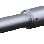
This broaching technique is known as rotary broaching because rotation plays a key part. Although no broaching machine is required, people who wish to try the method need a couple of special components: a rotary broach toolholder and a rotary broach. Common rotary broaches are made of high-speed steel, which is very hard and good for cutting a variety of metals. At the end of a rotary broach is a precision-ground form that matches the desired part shape.


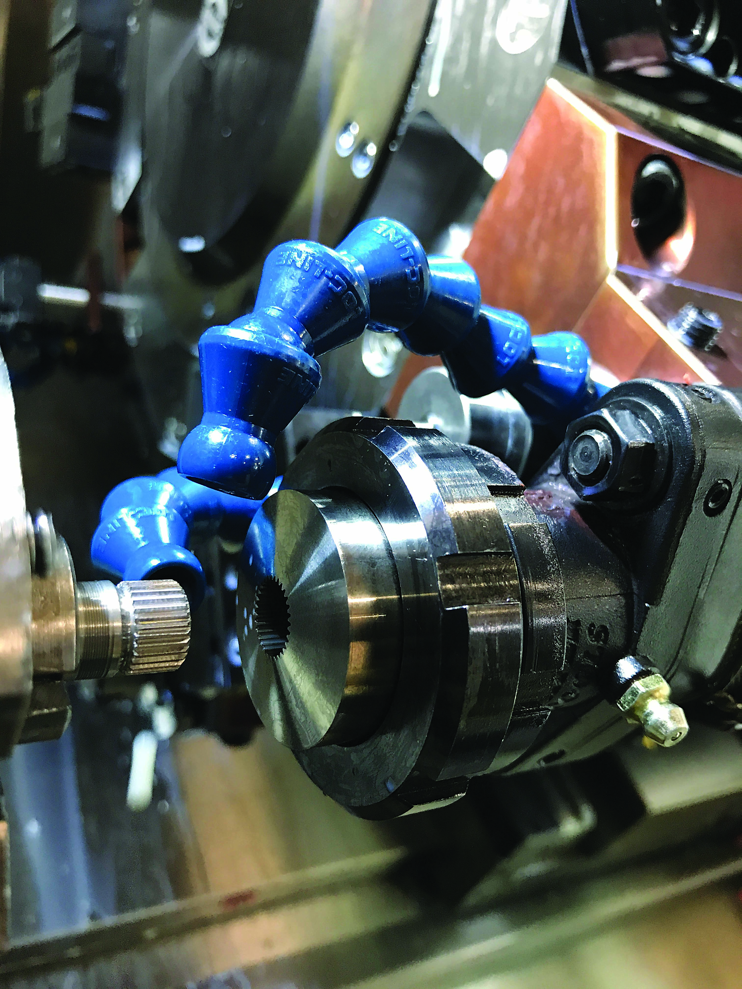
Rotary broaching tools machine a knurl on the OD of a steel part. Image courtesy of Slater Tools

Polygon Solutions Inc. in Fort Myers, Florida, makes sure the rotary broaches it sells don’t have sharp corners.

“Most of the time when a broach fails, it chips on a corner,” said President Steve Derbin. “So a corner radius helps.”

Process and Products

In a lathe, the rotary broach rotates 1-1 with the workpiece while the toolholder body remains stationary. The tooling is driven by the workpiece, so live tooling is not required.

The toolholder includes an internal live spindle that holds the broach at a 1-degree angle relative to the spindle. This produces a wobbly rotational motion, which is why rotary broaching also is known as wobble broaching. The result is chisellike action that rapidly cuts one corner of the shape at a time as the broach is fed through the workpiece to the finished depth.

The idea is to reduce pressure generated by the operation so it can be done on a CNC machine. Consider, for example, rotary broaching a hexagon form.

Although the entire form is created in a single pass, “there is not that much pressure because you are basically cutting out one corner at a time rather than putting the full form in at once,” Derbin explained.

When it comes to rotary broaching, he said, “all the magic is in the toolholder,” which features a freely rotating spindle on the front end supported by a set of bearings.

Rotary broach toolholders come in adjustable and adjustment-free styles.

“If you are using a really precise Swiss machine, you can just mount an adjustment-free holder in the machine and let it run while the adjustable will compensate for any machine misalignment,” said Kris Renner, director of operations at Clinton Township, Michigan-based Slater Tools Inc., which offers a variety of internal and external rotary broaches.

Adjustable holders can be centered right on the machine.

With rotary broaching, “we want to keep the pressure down, and centering is important for that reason,” Renner said.


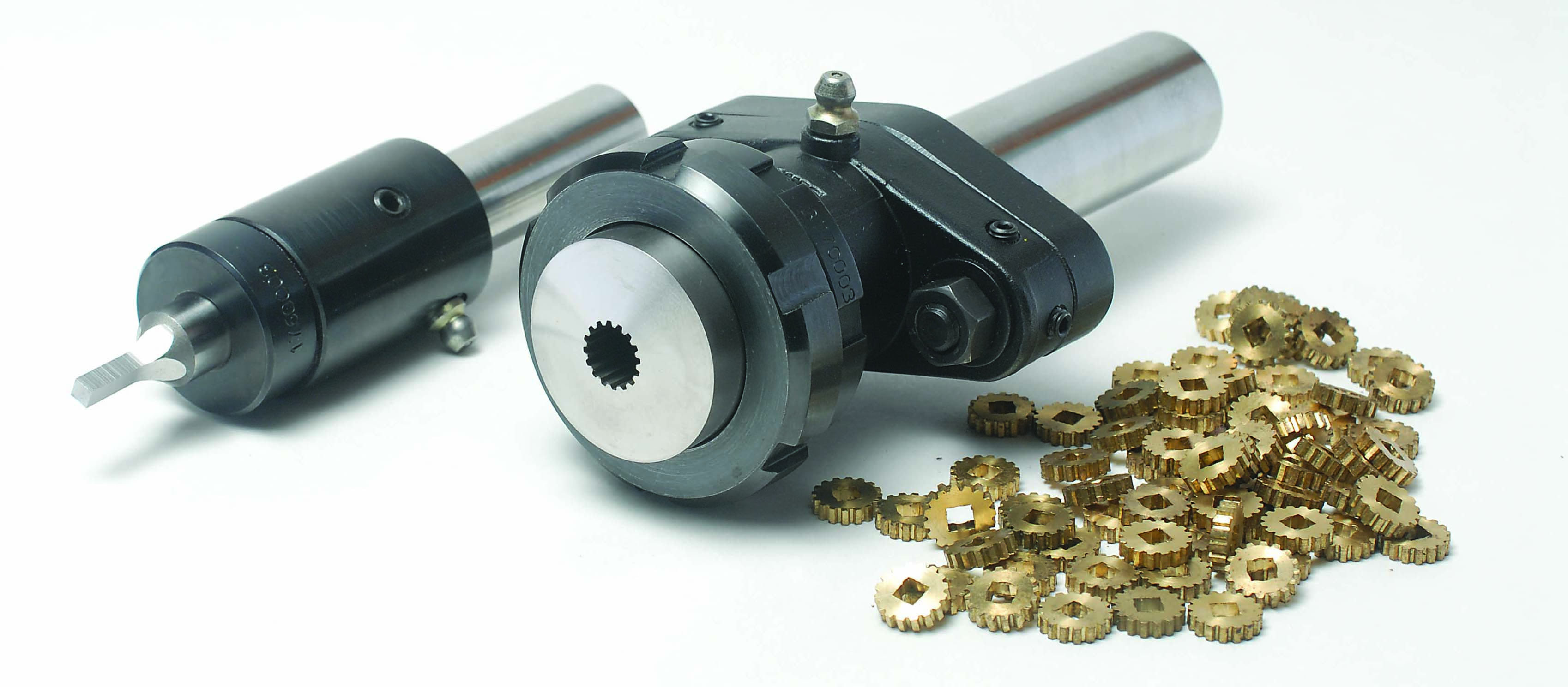
These rotary broaching tools produced an OD spline and ID square on brass parts. Image courtesy of Slater Tools

Rotary broaching can produce many internal and external forms. In addition to splines, keyways and hexagons, these include squares, serrations and Torx and Rosan types. Unlike broaching machines, rotary broaching can make internal forms in blind holes, as well as through-holes, Derbin said.

Why It Pays

Creating a shape with a broaching machine is a secondary operation performed after turning or milling the workpiece. By contrast, rotary broaching can be done on any lathe, mill or machining center at the same time as other operations. (In a mill, the rotary broach remains stationary with the workpiece on contact while the toolholder body rotates in the machine spindle.)

“In today’s machining world,” Renner said, “time is money, so that helps our customers be competitive.”

The same rotary broach toolholder can be used on a lathe or mill.

“It’s not machine-specific like a lot of toolholders,” Renner said. “We have people using it on super-old turret lathes and new and expensive five-axis vertical machining centers.”

A rotary broaching operation is completed in seconds and can create forms with an accuracy of 0.0127 mm (0.0005") or better. In some cases, thousands of parts can be broached before a tool change is necessary.

Nevertheless, Renner pointed out that conventional broaching is still popular in part because of the limitations of rotary broaching. For one thing, she said using rotary broaching to produce form sizes greater than approximately 50.8 mm (2") in diameter or forms that go deeper than about 1.5 times the major diameter would create so much pressure that it would trigger a CNC machine alarm.

In addition, rotary broaching workpieces made of materials over about 42 HRC “really takes a toll on tool life,” Derbin said. “You can do it, but you’re only going to get one or two parts per broach.”

Rotary Broaching Applied

Derbin reports that rotary broaching commonly is used today to create small features for the plumbing, medical and aerospace industries. For example, he noted that the technique is the only option for aerospace firms machining Rosan ports. These are blind holes, so the only other way they could be created is with wire electrical discharge machining. This process, however, produces so much heat that it can cause the ports to fracture.


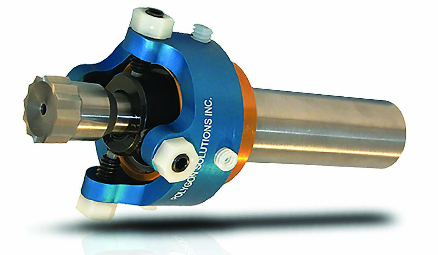
The blue alignment brake on the GT series rotary broach toolholder can orient a broach in the same position for each part. Image courtesy of Polygon Solutions

By contrast, rotary broaching is “a very low-heat operation,” he said.

In addition to cutting metal features, rotary broaching can be used on plastic workpieces. The good news about applying the process to plastics is that it’s not constrained by the same limits that exist when cutting metals.

“With plastics, either the chip kind of flakes off or they cut like butter,” Renner said. “So you aren’t going to have that pressure limitation that you have with something harder.”

This means that more material can be cut at one time and that broached forms can be larger and go deeper than what would be allowable with metals.

Not Standing Still

Rotary broaching is an old technology but hasn’t stood still over the years. Slater Tools, for example, has upgraded both its rotary broach materials and coatings over time.

“We are constantly working with new types of coatings,” Renner said, “and we do a lot of internal trials and research to make sure we are giving our customers the best solution for their particular application.”

The best solution, however, isn’t necessarily the hardest coating.

Sometimes an extremely hard coating “can create a cutting edge that is too brittle and will chip more readily,” Renner explained. “So it’s important that we do our research.”

At Polygon Solutions, Derbin and his colleagues have worked with metallurgists to develop proprietary heat-treating processes for rotary broaches. After heat treatment, the firm cryogenically freezes the blanks to bring the metal molecules back together and improve mechanical properties.

In addition, the company now offers both rougher and finisher broaches.


Rosan port rotary broaches are used widely in the aerospace industry. Image courtesy of Polygon Solutions

“If you have a bigger form, we can make you two broaches to go in back to back,” Derbin said. “You broach a rougher form and then broach the finishing form behind it. That reduces your chip load because now you are curling a couple of passes’ worth of chips instead of one big chip.”

By using combinations of rougher and finisher broaches, customers have been able to produce much larger teeth on forms like serrations and involute splines, he said.

As for toolholders, a major development at Polygon Solutions was the introduction of its GT series rotary broach toolholder. Adjustment-free GT series holders feature sealed bearings that don’t require greasing, as well as a pressure-relief hole in the side that matches up with a hole that runs through the broach being held. This small passageway allows hydraulic pressure to be relieved when a blind hole is being broached.

Follow Instructions

Before any rotary broaching process begins, shops should follow the part preparation instructions provided by equipment suppliers. To create an internal shape, for example, Slater Tools advises customers to pre-drill or pre-turn the workpiece to the diameter recommended for the application and add a lead-in chamfer to ensure gradual broach engagement with the workpiece.

“It’s all about creating a good-flowing chip and keeping the pressure down,” Renner said.

Although simple, proper part preparation is extremely important.

“It makes all the difference in the world,” Renner said. “If you don’t do it, you’re going to be banging your head against the wall.”    


Odd-Shaped Alternative

In some situations in which rotary broaching is used, machining firms might find that another option could save time and money, said Sean Doherty, technical sales team leader at Schwanog LLC in Elgin, Illinois.

For instance, Schwanog’s PWP broaching system can produce internal and external shapes, such as serrations, splines, hexagons and keyways, on CNC lathes with a c-axis. The system includes an insert ground to create the desired shape, a retaining screw and a steel toolholder.


The PWP system cuts an external shape. Image courtesy of Schwanog

To produce an external serrated surface with 40 teeth, for example, the company can grind an insert with 10 teeth that would complete the cutting in four passes, indexing 90 degrees after each pass. Machining of a serrated part made of 1045 steel can be completed in just seven seconds, according to the company.

Customers have told Doherty that a custom rotary broach costs over $100, a holder system costs a few hundred dollars and delivery times run from five to eight weeks. By contrast, he noted, Schwanog’s custom-ground inserts usually cost around $50 to $80, depending on the quantity ordered, and holders are roughly $100 for most outer-diameter broaching applications while lead times are only three to four weeks.

In addition, he said the fact that Schwanog tools don’t encapsulate the whole part or cover the entire inner-diameter area helps with chip control.

“Chips have a place to go,” Doherty said, “and coolant can flow in there and flush out parts.”

William Leventon


For more information about broaching, view a video presentation from Schwanog at cteplus.delivr.com/2cta2


Related Glossary Terms

  • broach

    broach

    Tapered tool, with a series of teeth of increasing length, that is pushed or pulled into a workpiece, successively removing small amounts of metal to enlarge a hole, slot or other opening to final size.

  • broaching

    broaching

    Operation in which a cutter progressively enlarges a slot or hole or shapes a workpiece exterior. Low teeth start the cut, intermediate teeth remove the majority of the material and high teeth finish the task. Broaching can be a one-step operation, as opposed to milling and slotting, which require repeated passes. Typically, however, broaching also involves multiple passes.

  • broaching machine

    broaching machine

    Machine designed specifically to run broaching tools. It is typically designated by operating characteristics (pull, push, rotary, continuous, blind-spline), type of power used (hydraulic, mechanical) and tonnage ratings. Broaching is also performed on arbor presses (manual and powered).

  • centering

    centering

    1. Process of locating the center of a workpiece to be mounted on centers. 2. Process of mounting the workpiece concentric to the machine spindle. See centers.

  • centers

    centers

    Cone-shaped pins that support a workpiece by one or two ends during machining. The centers fit into holes drilled in the workpiece ends. Centers that turn with the workpiece are called “live” centers; those that do not are called “dead” centers.

  • computer numerical control ( CNC)

    computer numerical control ( CNC)

    Microprocessor-based controller dedicated to a machine tool that permits the creation or modification of parts. Programmed numerical control activates the machine’s servos and spindle drives and controls the various machining operations. See DNC, direct numerical control; NC, numerical control.

  • coolant

    coolant

    Fluid that reduces temperature buildup at the tool/workpiece interface during machining. Normally takes the form of a liquid such as soluble or chemical mixtures (semisynthetic, synthetic) but can be pressurized air or other gas. Because of water’s ability to absorb great quantities of heat, it is widely used as a coolant and vehicle for various cutting compounds, with the water-to-compound ratio varying with the machining task. See cutting fluid; semisynthetic cutting fluid; soluble-oil cutting fluid; synthetic cutting fluid.

  • gang cutting ( milling)

    gang cutting ( milling)

    Machining with several cutters mounted on a single arbor, generally for simultaneous cutting.

  • heat-treating

    heat-treating

    Process that combines controlled heating and cooling of metals or alloys in their solid state to derive desired properties. Heat-treatment can be applied to a variety of commercially used metals, including iron, steel, aluminum and copper.

  • inner diameter ( ID)

    inner diameter ( ID)

    Dimension that defines the inside diameter of a cavity or hole. See OD, outer diameter.

  • lathe

    lathe

    Turning machine capable of sawing, milling, grinding, gear-cutting, drilling, reaming, boring, threading, facing, chamfering, grooving, knurling, spinning, parting, necking, taper-cutting, and cam- and eccentric-cutting, as well as step- and straight-turning. Comes in a variety of forms, ranging from manual to semiautomatic to fully automatic, with major types being engine lathes, turning and contouring lathes, turret lathes and numerical-control lathes. The engine lathe consists of a headstock and spindle, tailstock, bed, carriage (complete with apron) and cross slides. Features include gear- (speed) and feed-selector levers, toolpost, compound rest, lead screw and reversing lead screw, threading dial and rapid-traverse lever. Special lathe types include through-the-spindle, camshaft and crankshaft, brake drum and rotor, spinning and gun-barrel machines. Toolroom and bench lathes are used for precision work; the former for tool-and-die work and similar tasks, the latter for small workpieces (instruments, watches), normally without a power feed. Models are typically designated according to their “swing,” or the largest-diameter workpiece that can be rotated; bed length, or the distance between centers; and horsepower generated. See turning machine.

  • machining center

    machining center

    CNC machine tool capable of drilling, reaming, tapping, milling and boring. Normally comes with an automatic toolchanger. See automatic toolchanger.

  • mechanical properties

    mechanical properties

    Properties of a material that reveal its elastic and inelastic behavior when force is applied, thereby indicating its suitability for mechanical applications; for example, modulus of elasticity, tensile strength, elongation, hardness and fatigue limit.

  • milling

    milling

    Machining operation in which metal or other material is removed by applying power to a rotating cutter. In vertical milling, the cutting tool is mounted vertically on the spindle. In horizontal milling, the cutting tool is mounted horizontally, either directly on the spindle or on an arbor. Horizontal milling is further broken down into conventional milling, where the cutter rotates opposite the direction of feed, or “up” into the workpiece; and climb milling, where the cutter rotates in the direction of feed, or “down” into the workpiece. Milling operations include plane or surface milling, endmilling, facemilling, angle milling, form milling and profiling.

  • milling machine ( mill)

    milling machine ( mill)

    Runs endmills and arbor-mounted milling cutters. Features include a head with a spindle that drives the cutters; a column, knee and table that provide motion in the three Cartesian axes; and a base that supports the components and houses the cutting-fluid pump and reservoir. The work is mounted on the table and fed into the rotating cutter or endmill to accomplish the milling steps; vertical milling machines also feed endmills into the work by means of a spindle-mounted quill. Models range from small manual machines to big bed-type and duplex mills. All take one of three basic forms: vertical, horizontal or convertible horizontal/vertical. Vertical machines may be knee-type (the table is mounted on a knee that can be elevated) or bed-type (the table is securely supported and only moves horizontally). In general, horizontal machines are bigger and more powerful, while vertical machines are lighter but more versatile and easier to set up and operate.

  • outer diameter ( OD)

    outer diameter ( OD)

    Dimension that defines the exterior diameter of a cylindrical or round part. See ID, inner diameter.

  • toolholder

    toolholder

    Secures a cutting tool during a machining operation. Basic types include block, cartridge, chuck, collet, fixed, modular, quick-change and rotating.

  • turning

    turning

    Workpiece is held in a chuck, mounted on a face plate or secured between centers and rotated while a cutting tool, normally a single-point tool, is fed into it along its periphery or across its end or face. Takes the form of straight turning (cutting along the periphery of the workpiece); taper turning (creating a taper); step turning (turning different-size diameters on the same work); chamfering (beveling an edge or shoulder); facing (cutting on an end); turning threads (usually external but can be internal); roughing (high-volume metal removal); and finishing (final light cuts). Performed on lathes, turning centers, chucking machines, automatic screw machines and similar machines.

Contributors

Polygon Solutions Inc.
239-628-4800
www.polygonsolutions.com

Slater Tools Inc.
586-465-5000
www.slatertools.com