The proliferation of aluminum in the automotive sector continues to surge. Not long ago, aluminum components were rare; now, they can make up 30% of a vehicle’s weight. From engine blocks and gearbox housings to oil pans and battery racks, many of these aluminum components require exact roughness and crosshatch patterns to provide proper surfaces for gasket and sealant adhesion. Seemingly miniscule differentials in surface topography —also known as framed roughness — can affect the ability of sealants to adhere, impacting the quality of the seal and, ultimately, the viability of the entire part.
Meeting strict surface roughness guidelines in aluminum requires precise measurement, a careful machining approach and cutting tools optimized for the task. The right combination of these key elements can boost machine shop productivity while producing reliable, gasket- grade components.
To guide you down that path, here are six steps that will help you achieve a gasket-grade surface finish in aluminum.
1. Measure roughness correctly
Most manufacturers have in-house measuring devices that can provide accurate Ra (arithmetical mean roughness) and Rz (mean roughness depth) values. Use them. Even experienced machinists should not rely on their eyes or fingertips where surface topography is concerned. Throughout the machining process, verify the framed roughness with precision instruments to promote long-term component dependability.
2. Program to reduce smear
When an indexable milling tool first enters the material, it can create an irregular, unintentional “smear” if not executed carefully. The same risk holds for the cutting tool’s exit path. These smears present hazards to the roughness profile and the overall integrity of the component by forming pockets where oil or fluid can pool. Programming a slight taper into the cutting path or beginning each pass with the back side of the cutter can mitigate these risks. Work with your tooling provider to determine the proper programming techniques for your tool and the component in question.
3. Get creative with coolant
In automotive applications — especially in the electric vehicle space — coolant-free machining is becoming commonplace for components like battery trays, where even a small amount of coolant residue can lead to problems downstream. Properly cooling the cutting zone will lead to a more precise roughness profile while also helping to control chips and reduce burrs. Instead of standard coolant, consider using minimum quantity lubrication (MQL) — or even pressurized air — in battery-facing components to keep the surface at a workable temperature.
4. Leverage a specialized cutter
Component production order size and time constraints can dictate which cutting tool is ideal for the job. For small batches or prototypes, an off-the-shelf, square-shoulder indexable face mill made with polycrystalline diamond (PCD) material will suffice. In high-volume scenarios, opt for a more optimized rotary broach tool capable of creating scratch surfaces at faster cycle times.
Additionally, while many machinists intuitively gravitate toward a smaller cutter, consider utilizing a larger cutter body. Larger tools may slightly increase cycle time, but they more than compensate by providing better control, reducing errors and creating a more uniform surface finish.
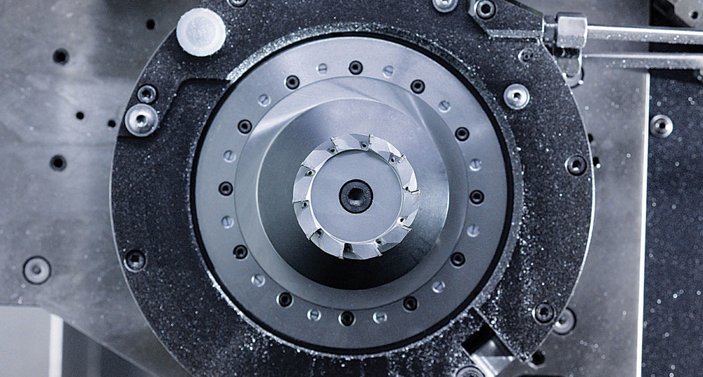
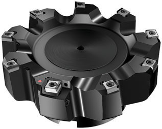 Milling cutters, such as the CoroMill M5F90 and M5B90FR from Sandvik Coromant, can create gasket-grade surfaces in aluminum components, like flange faces. Sandvik Coromant
 Milling cutters, such as the CoroMill M5F90 and M5B90FR from Sandvik Coromant, can create gasket-grade surfaces in aluminum components, like flange faces. Sandvik Coromant
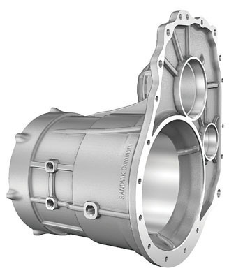
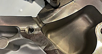 Aluminum components like housings require particular framed roughness and crosshatching for gasket adherence. Sandvik Coromant
 Aluminum components like housings require particular framed roughness and crosshatching for gasket adherence. Sandvik Coromant
5. Deploy a mixed-insert solution
Making use of each pocket where inserts slot into the cutting tool head can streamline the scratching process. For example, a manufacturer might use general-purpose PCD inserts in nine of the 10 pockets in the tool head, and a special scratching insert with a slightly different geometry in the remaining pocket. Alternatively, dropping a wiper insert 10 μm to 20 μm below a scratching insert (or vice versa) can give the component its trademark shine while the roughness profile is being shaped. These techniques can create ideal surface topography in fewer passes. Remember that aluminum with high silica content or other additives can be hard on cutting tools, so select your inserts accordingly.
6. Partner with a qualified tool provider
At every stage of the machining process, whether roughing or finishing, the right tooling partner can provide guidance and recommendations for the proper cutting heads, inserts and grades, coatings and geometries, and even toolpaths. These insights can translate to real cost and time savings on the shop floor, optimizing production while ensuring the gasket finish meets exact roughness specifications.
Related Glossary Terms
- broach
broach
Tapered tool, with a series of teeth of increasing length, that is pushed or pulled into a workpiece, successively removing small amounts of metal to enlarge a hole, slot or other opening to final size.
- coolant
coolant
Fluid that reduces temperature buildup at the tool/workpiece interface during machining. Normally takes the form of a liquid such as soluble or chemical mixtures (semisynthetic, synthetic) but can be pressurized air or other gas. Because of water’s ability to absorb great quantities of heat, it is widely used as a coolant and vehicle for various cutting compounds, with the water-to-compound ratio varying with the machining task. See cutting fluid; semisynthetic cutting fluid; soluble-oil cutting fluid; synthetic cutting fluid.
- gang cutting ( milling)
gang cutting ( milling)
Machining with several cutters mounted on a single arbor, generally for simultaneous cutting.
- milling
milling
Machining operation in which metal or other material is removed by applying power to a rotating cutter. In vertical milling, the cutting tool is mounted vertically on the spindle. In horizontal milling, the cutting tool is mounted horizontally, either directly on the spindle or on an arbor. Horizontal milling is further broken down into conventional milling, where the cutter rotates opposite the direction of feed, or “up” into the workpiece; and climb milling, where the cutter rotates in the direction of feed, or “down” into the workpiece. Milling operations include plane or surface milling, endmilling, facemilling, angle milling, form milling and profiling.
- milling machine ( mill)
milling machine ( mill)
Runs endmills and arbor-mounted milling cutters. Features include a head with a spindle that drives the cutters; a column, knee and table that provide motion in the three Cartesian axes; and a base that supports the components and houses the cutting-fluid pump and reservoir. The work is mounted on the table and fed into the rotating cutter or endmill to accomplish the milling steps; vertical milling machines also feed endmills into the work by means of a spindle-mounted quill. Models range from small manual machines to big bed-type and duplex mills. All take one of three basic forms: vertical, horizontal or convertible horizontal/vertical. Vertical machines may be knee-type (the table is mounted on a knee that can be elevated) or bed-type (the table is securely supported and only moves horizontally). In general, horizontal machines are bigger and more powerful, while vertical machines are lighter but more versatile and easier to set up and operate.
- polycrystalline diamond ( PCD)
polycrystalline diamond ( PCD)
Cutting tool material consisting of natural or synthetic diamond crystals bonded together under high pressure at elevated temperatures. PCD is available as a tip brazed to a carbide insert carrier. Used for machining nonferrous alloys and nonmetallic materials at high cutting speeds.
- polycrystalline diamond ( PCD)2
polycrystalline diamond ( PCD)
Cutting tool material consisting of natural or synthetic diamond crystals bonded together under high pressure at elevated temperatures. PCD is available as a tip brazed to a carbide insert carrier. Used for machining nonferrous alloys and nonmetallic materials at high cutting speeds.
- wiper
wiper
Metal-removing edge on the face of a cutter that travels in a plane perpendicular to the axis. It is the edge that sweeps the machined surface. The flat should be as wide as the feed per revolution of the cutter. This allows any given insert to wipe the entire workpiece surface and impart a fine surface finish at a high feed rate.