Thinking About Automation?
Thinking About Automation?
Shops new to automation can start with turning. Simple tools like bar feeders, tool monitoring, redundancy, and probing create stable, unattended processes.
For several years now, manufacturers and machine shops have lamented the shortage of skilled employees. The general opinion from business leaders is that this trend is only going to continue.
One of the surest ways to overcome these challenges is by automating machining processes. Automating can seem like a daunting task to those who have not been exposed to automated machining processes, but it's much simpler than it appears. Knowing where to start and having a basic roadmap is usually all it takes for a creative machinist or engineer to begin automating.
It is important to remember that there are degrees of automation from very advanced to very simple, but the goal is always the same — to reduce human intervention.
For shops that have never automated machining processes the best place to start is with turning operations, which are less complex and require fewer inputs than most milling operations. Turning operations will usually have fewer tools, a single work offset and CNC turning centers usually come from the factory with the necessary options.
If you have a machine tool with a control that has been manufactured in the last decade there are only a few things that you need to do to begin automating your turning processes.
Cost-effective automation
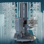
Automating the turning process requires having a reliable method of delivering stock to the spindle. It is common to see a turning center feeding a piece of bar through the spindle and cutting off the finished part. This is commonly referred to as "bar work," which is the most common way to automate a turning process. Bar feeders are used to feed the bar stock through the spindle so the lathe can run in a continuous loop. Bar feeders are relatively inexpensive and very flexible, and that makes them a good investment for the shop that wants to automate.
In lieu of a bar feeder, a shop can use a bar puller. They are simple devices that mount in the turret and grasp the stock while the turret pulls the stock forward for the next part. It's a poor man's bar feeder. Both methods are effective and easy ways to introduce automation to a shop.
Doing bar work will require a cut-off operation in the turning process. A parts catcher for the machine is a valuable option to add for this kind of work. The catcher is actuated when it's time to cut the part off, and, once complete, the part is ejected outside of the machine. While not absolutely necessary, a parts catcher is a clean and safe way to get finished parts out of the machine.
When bar work is not possible, then the workpiece has to be loaded another way. This is where robots and gantry loaders are utilized. Machines with robots and gantries are complex and not very flexible. They are also expensive and the integration of the loading device and the turning process can be complex. Therefore, robots and gantries may be out of reach for some shops, forcing them to load parts manually.
Loading parts manually does not qualify as "fully automated," but may be necessary for a shop that is implementing the steps to reach full automation. Implementing some of the tools mentioned below will lay the foundation for implementing advanced part loading later.
Tool monitoring
Automating a turning process is going to require some kind of tool life monitoring. It is critical that the machine can be signaled to stop when a tool reaches the end of its life. Breaking a tool while running unattended can be catastrophic.
Tool monitoring in the most basic form utilizes timers or part counts to signal the machine to cease operation when the allowable limits have been reached. More complex processes will utilize tool probes to measure the tool and monitor wear. The most sophisticated machines will monitor power consumption to detect worn tools. While complex tool monitoring systems have many benefits, the onboard timers and part counters are sufficient to create a stable automated process.
Have the next tool ready on the turret
Not only is it necessary to employ some sort of tool life monitoring, it is important to "tool-up" the machine in a manner that promotes the goal of reduced intervention. Once a tool has timed out, having a second or third just like it in the turret allows the tool management system to retrieve the redundant tools so the machine doesn't stop.
The biggest drawback to redundant tools is not having enough open spaces on the turret. This can be overcome with some creativity. Utilizing form tools that make multiple features or replacing standard turning tools with groove-turn tools. In other cases, it might be necessary to use a standard tool in an unorthodox manner, like chamfering with a threading tool or turning an outside diameter with a boring bar. Getting the maximum number of tools in the turret is the goal. The more tools there are in the turret, the less a machinist has to intervene in the process.
Probing for accuracy and long tool life
Part probes are not necessary for automation but they certainly make life a lot better. Having a probe on board allows the machine to measure critical dimensions. When the dimensions deviate from the specification the machine can automatically adjust offsets to correct the condition.
Data from the probe can also be used in conjunction with tool life management to trigger actions that prevent scrap and damage. Probes can also be used to evaluate other conditions, such as the diameter of the raw material to ensure the correct work piece is loaded into the machine. Integrating a part probe into an automation project is one of the best ways to build a stable and repeatable turning process.
Building reliable, repeatable automation
These are foundational steps that a shop can begin doing to automate, and most of these can be done with minimal investment. Again, the goal is to identify and automate process steps that require a person to interact with the machine. By methodically identifying and automating these activities, shops will build repeatable turning processes that can be left to run unattended, and, ultimately, generate increased profits by reducing costs. Automated turning processes are a force multiplier allowing shops to produce more work without increasing headcount.