Understanding tapered spindle connections

Author Dr. Scott Smith
Published
December 01, 2014 - 10:30am

Cutting tools are most commonly mounted in a machine tool spindle using toolholders, which provide the interface between a variety of cutting tool geometries and the common spindle nose. While some tools connect directly to the spindle via bolting, for example, that is unusual.

Toolholders simultaneously adapt the tool geometry, provide accurate tool location, enable tool retention and transmit torque, thrust and bending forces. Toolholders, sometimes called adapters, must provide stiff, repeatable connections. A cone-type geometry is an obvious choice because a cone is rotationally symmetric and self-centering. That is, if the toolholder is inserted into the spindle nose with a slight misalignment, the contact of the holder with the nose produces a force that tends to straighten and center the holder. Cone-type toolholders are generally made of steel and casehardened, so the outer surface is hard while the underlying material provides toughness.

Cone-type toolholders come in two basic types: self-locking and free-releasing. In a self-locking holder, the included angle of the cone is small (the cone seems sharp).These devices are sometimes called shallow-taper holders; when a tool is inserted into the spindle nose, friction and other forces are sufficient to hold the tool in the spindle and to transmit the forces and torques.

A special tool is often necessary to knock a holder out of the spindle. One of the most common self-locking tapers is the Morse taper. This holder tapers at a rate of about ⅝" (15.875mm) per foot of axial length. It often incorporates a tang on the end to facilitate knockout using a thin wedge called a drift, which is driven through a hole in the side of the spindle. Other self-locking taper geometries include Jacobs and Brown & Sharpe.

Figure%201.tif

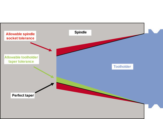
Courtesy of S. Smith

Figure 1. The tolerance zones for 7/24 steep-taper toolholders.

When automatic toolchangers became more common, especially with the advent of NC machining, the manual knockout process became cumbersome. Therefore, machinists prefer toolholders that do not self-lock in the spindle. These holders have a cone that tapers at 3.5 " (88.9mm) per foot and are often called 7/24 tapers (7 " of taper per 24 " of axial length), or steep tapers.

Many standard holders, such as CAT, ISO and BT, use the 7/24 cone, but differ in other particulars, such as flanges and pull studs. The standard sizes of this cone, such as 30, 40, 50 and 60, have the same cone angle, but are sections at different places along the length of the cone, with 30 being smaller and 60 being larger.

While the female cone of the spindle nose and the male cone of the holder are conceptually perfect, it is clearly not possible to make a perfect cone in either case. Many properties of the connection—including self-locking ability, stiffness, damping, accuracy and repeatability—depend on the accuracy of the manufactured cone. For steep-taper connections, two standards, ANSI/ASME B5.50-1994 and ISO 1947, define tolerance classes that run from AT1 to AT11, with AT1 being the tightest tolerance.

Figure 1 shows the perfect fit between a toolholder and spindle nose as a black line. The allowable error in the spindle nose is shown in red, and the allowable error in the toolholder body is shown in green. The tolerances are arranged to ensure there is contact between the toolholder and spindle near the gage line, and any errors allow for a clearance at the tail of the toolholder near the retention knob.

The AT classes specify a zone into which the geometry of the machined taper must fit. The classes are not linearly related and become increasingly more difficult to achieve as the class number decreases. Most machine tool spindles have a taper of Class AT2 or better, while most toolholders are Class AT3 or better.

The performance of the connection depends largely on the class of fit and surface quality. It is important to treat the toolholders like the precision pieces of equipment they are. Most high-performance toolholders have a ground surface, and it is poor practice to allow that surface to rust or become otherwise damaged.

For tight-tolerance holders, something as simple as overtightening the retention knob can cause the tail end of the holder to swell, changing the class of fit and moving the contact in the spindle from the nose to the tail. Loss of contact at the nose dramatically reduces the stiffness and can damage the holder and spindle. The retention knob should be torqued to the manufacturer’s specifications using a torque wrench or a torque fixture. CTE

About the Author: Dr. Scott Smith is a professor and chair of the Department of Mechanical Engineering at the William States Lee College of Engineering, University of North Carolina at Charlotte, specializing in machine tool structural dynamics. Contact him via e-mail at kssmith@uncc.edu.

Related Glossary Terms

  • clearance

    clearance

    Space provided behind a tool’s land or relief to prevent rubbing and subsequent premature deterioration of the tool. See land; relief.

  • fixture

    fixture

    Device, often made in-house, that holds a specific workpiece. See jig; modular fixturing.

  • included angle

    included angle

    Measurement of the total angle within the interior of a workpiece or the angle between any two intersecting lines or surfaces.

  • knockout

    knockout

    Mechanism for releasing workpieces from a die. It is also called ejector, kickout, liftout or shedder.

  • numerical control ( NC)

    numerical control ( NC)

    Any controlled equipment that allows an operator to program its movement by entering a series of coded numbers and symbols. See CNC, computer numerical control; DNC, direct numerical control.

  • stiffness

    stiffness

    1. Ability of a material or part to resist elastic deflection. 2. The rate of stress with respect to strain; the greater the stress required to produce a given strain, the stiffer the material is said to be. See dynamic stiffness; static stiffness.

  • tang

    tang

    Extended flat portion of tapered drill shank, endmill or other tool that allows maximum power transmission and proper positioning of the tool. Reverse shape of the machine-spindle slot into which it fits.

  • tolerance

    tolerance

    Minimum and maximum amount a workpiece dimension is allowed to vary from a set standard and still be acceptable.

  • toolholder

    toolholder

    Secures a cutting tool during a machining operation. Basic types include block, cartridge, chuck, collet, fixed, modular, quick-change and rotating.

Author

Dr. Scott Smith is a professor and chair of the Department of Mechanical Engineering at the William States Lee College of Engineering, University of North Carolina at Charlotte, specializing in machine tool structural dynamics. Contact him via e-mail at kssmith@uncc.edu.

Click on the author to view all of their articles!