Spiral Machining

Author Cutting Tool Engineering
Published
August 19, 2025 - 07:00pm
view magazine
Machinist’s Corner

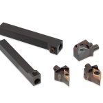
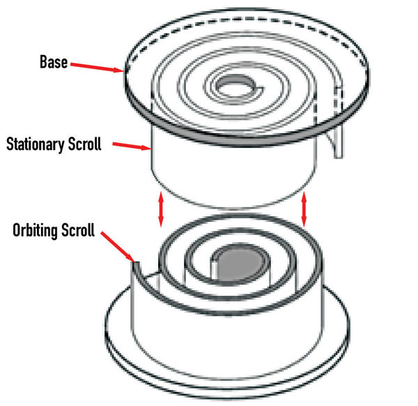
There has been an increase in demand for scroll, or spiral, compressors as the accuracy of the methods used to make them have improved. Scroll compressors are used to compress refrigerant or air to create vacuums. A scroll compressor has two Archimedes spirals nested together. Figure 1 shows components of a scroll compressor, and figure 2 shows how it works. The gas enters at two places on the outside of the scrolls and exits through a hole at the center of the fixed scroll. Patented in 1905 by Leon Creux, this is an example of an inventor being way ahead of the curve. Creux could never make a unit that worked. The way that a scroll compressor seals in the gas is the conundrum. In figure 1, the open ends of the helixes have a groove to accept O-ring material that sets against the base of the other spiral. That seals the unit axially. Radially the unit is sealed by the gap between the stationary and orbiting spirals. The smaller the gap, the better the seal and efficiency of pumping. But if they touch, it is trouble.

The efficiency is determined by pumping losses. The closer the outer surface of the inner scroll comes to the inside surface of the outer scroll, the less leakage there will be. This phenomenon is mathematically explained by exponential functions — so microns matter.

A spiral is a curve whose radius is equal to a constant multiplied by an angular displacement from zero. It is a continuous curve — not an arc or a straight line, and not a bunch of little steps like Stepper motors make. Servo motor drives are better in this application because they produce continuous motion. Using G code to interpolate a spiral tool path moving in two linear axes is an approximation. And as the size of the spiral decreases, the amount of approximation increases. Also, when milling machine axes change direction, there is a backlash error. Ball screws have backlash.

A very accurate spiral tool path can be generated using a CNC rotary table in conjunction with one axis of linear motion on a CNC milling machine. The milling cutter is positioned at the beginning of the cut. Now constant feed rate linear motion of the milling machine is interpolated with constant feed rate rotary motion of the rotary table until the end of the spiral cut. The axes of motion do not change direction, so there is no backlash error. And, since the feed rates are constant, there is no interpolation error. Now the tool path error is the pitch error of the milling machine’s ball screw coupled with the radial runout of the rotary table. Switzerland- based pL LEHMANN makes rotary tables with a radial runout of 2-3 microns, or about 0.0001". Milling machines are made with a lead screw pitch error of that magnitude. Now the tool path error is 0.0002" or less. Pretty good.

image of Components of a scroll compressor Figure 1: Components of a scroll compressor.

Using one feed rate over the whole cut will produce ever increasing or decreasing chip load. In order to get a more even chip load and, hence, more consistent surface finish, the programmed motion can be divided into segments with increasing or decreasing feed rates for both linear and rotary motion.

This machining process is also much simpler to program than spiral interpolation.

As I have said before, an accurate tool is a good tool; an inaccurate tool is an expensive tool.

Related Glossary Terms

  • backlash

    backlash

    Reaction in dynamic motion systems where potential energy that was created while the object was in motion is released when the object stops. Release of this potential energy or inertia causes the device to quickly snap backward relative to the last direction of motion. Backlash can cause a system’s final resting position to be different from what was intended and from where the control system intended to stop the device.

  • computer numerical control ( CNC)

    computer numerical control ( CNC)

    Microprocessor-based controller dedicated to a machine tool that permits the creation or modification of parts. Programmed numerical control activates the machine’s servos and spindle drives and controls the various machining operations. See DNC, direct numerical control; NC, numerical control.

  • feed

    feed

    Rate of change of position of the tool as a whole, relative to the workpiece while cutting.

  • gang cutting ( milling)

    gang cutting ( milling)

    Machining with several cutters mounted on a single arbor, generally for simultaneous cutting.

  • interpolation

    interpolation

    Process of generating a sufficient number of positioning commands for the servomotors driving the machine tool so the path of the tool closely approximates the ideal path. See CNC, computer numerical control; NC, numerical control.

  • milling

    milling

    Machining operation in which metal or other material is removed by applying power to a rotating cutter. In vertical milling, the cutting tool is mounted vertically on the spindle. In horizontal milling, the cutting tool is mounted horizontally, either directly on the spindle or on an arbor. Horizontal milling is further broken down into conventional milling, where the cutter rotates opposite the direction of feed, or “up” into the workpiece; and climb milling, where the cutter rotates in the direction of feed, or “down” into the workpiece. Milling operations include plane or surface milling, endmilling, facemilling, angle milling, form milling and profiling.

  • milling cutter

    milling cutter

    Loosely, any milling tool. Horizontal cutters take the form of plain milling cutters, plain spiral-tooth cutters, helical cutters, side-milling cutters, staggered-tooth side-milling cutters, facemilling cutters, angular cutters, double-angle cutters, convex and concave form-milling cutters, straddle-sprocket cutters, spur-gear cutters, corner-rounding cutters and slitting saws. Vertical cutters use shank-mounted cutting tools, including endmills, T-slot cutters, Woodruff keyseat cutters and dovetail cutters; these may also be used on horizontal mills. See milling.

  • milling machine ( mill)

    milling machine ( mill)

    Runs endmills and arbor-mounted milling cutters. Features include a head with a spindle that drives the cutters; a column, knee and table that provide motion in the three Cartesian axes; and a base that supports the components and houses the cutting-fluid pump and reservoir. The work is mounted on the table and fed into the rotating cutter or endmill to accomplish the milling steps; vertical milling machines also feed endmills into the work by means of a spindle-mounted quill. Models range from small manual machines to big bed-type and duplex mills. All take one of three basic forms: vertical, horizontal or convertible horizontal/vertical. Vertical machines may be knee-type (the table is mounted on a knee that can be elevated) or bed-type (the table is securely supported and only moves horizontally). In general, horizontal machines are bigger and more powerful, while vertical machines are lighter but more versatile and easier to set up and operate.

  • pitch

    pitch

    1. On a saw blade, the number of teeth per inch. 2. In threading, the number of threads per inch.