Automatic recessing heads make any precision grooving operation fast and easy.
Machining a groove or undercut in the wall of a drilled or bored hole can be a difficult and time-consuming operation, especially for multiple parts. Automatic recessing heads offer a solution for cutting grooves in any type of metalworking material. These heads can produce grooves for O-rings or retaining rings, or grooves shaped for special applications. The shape and width of the grooves are strictly controlled by the geometry ground into the cutter. The cutter may be made of HSS or brazed carbide, or it may consist of a holder and an indexable carbide insert.
Recessing heads may be used in drill presses, lathes, mills, boring machines, and even multispindle automatics. Typically, the recessing operation can be run at the feed and speed recommended for the type of operation and the tool material and workpiece material being used. However, the feed and speed also may depend on the size and rigidity of the machine. Most heads are used in rotary-tool applications on mills or drill presses.
Operating Principle
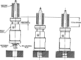
Figure 1: Operating principle of an automatic recessing head, including approach stroke (A), feed stroke (B), and end of feed stroke (C)
The recessing operation can be divided into three stages: approach stroke, feed stroke, and end of feed stroke (Figure 1). On a drill press, for example, the tool is rotating in the machine spindle during the approach stroke. The spindle is lowered, and the tool moves into position.
During the feed stroke, the cutter enters the hole in a retracted position while rotating with the machine spindle. The head typically has a pilot mounted on a bearing. The pilot is designed for one specific hole; to groove a different size of hole, the user would change the pilot as well as the cutter.
When the pilot contacts the face of the workpiece, further downward movement of the cutter is stopped. As the machine spindle continues downward, the recessing head is compressed, thereby actuating the mechanism inside the recessing head that translates the motion through 90°, causing the cutter to feed out into the work. In many recessing heads, the cutter moves out radially; in other types, the cutter moves out as on an eccentric.
The correct depth of cut (DOC) is obtained at the end of the feed stroke when the micrometer stop bottoms against the top of the outer body. The adjustable stop limits the amount of compression, which in turn defines the final position of the cutter and controls the depth of the groove. Groove location is controlled by a set screw in the shank end of the cutter.
Recessing Advantages
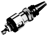
Figure 2: Automatic recessing head for machining centers.
Alternative methods of machining grooves in holes each have significant drawbacks. For example, a grooving operation done on a CNC milling machine using circular interpolation can be extremely time-consuming compared to cutting the same groove with an automatic recessing tool designed specifically for CNC machining centers with automatic toolchangers. On average, a recessing head such as that in Figure 2 will do the job in about half the time that circular interpolation requires. This type of head may be provided with or without a micrometer stop, since the DOC can be controlled by the Z-axis on the CNC machine.
Other alternatives include manual machining methods such as chucking the part in a lathe and using a boring bar to cut the groove, or grooving with a boring head in a milling machine. However, using recessing heads on manual machines allows grooves to be cut in multiple parts more quickly and with less difficulty than these methods.
Imagine using a boring head in a milling machine for a grooving operation. The operator must position the cutter for the right depth into the bore, manually feed the boring head to produce the correct diameter groove, and then bring the cutter back to clear the hole and repeat on the next piece. The same would apply if using an engine lathe; the cutter must be positioned properly inside the bore, and then the cross slide must be fed out to the proper depth. Accuracy is dependent on the operator’s skill.
With an automatic recessing head on a mill or engine lathe, the operator simply lines up the component bore and compresses the head. When the spindle is retracted, the pressure is relieved, the cutter is fully retracted, and the tool is withdrawn from the bore. The job is done accurately time after time, regardless of the operator’s skill.
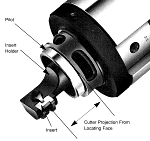
Figure 3: The cutter projection from the locating face can be set to accurately locate the groove in the hole.
Another advantage of using a recessing head is that the cutter can be precisely positioned relative to the pilot to accurately locate the groove in the hole wall. By turning a set screw in the shank end of the cutter, the cutter can be adjusted to project the desired length from the pilot or tool body. Dial calipers or a tool presetter can be used to set this projection so that the groove will be properly located in the hole (Figure 3).
In addition to controlling the location of the groove, a recessing head accurately controls the depth of the groove, or how far the tool cuts into the workpiece. The micrometer stop controls the distance from the beginning to the end of the feed stroke, which is the degree to which the tool body can be compressed. A fixed ratio built into the tool’s mechanism governs how much cutter motion will result from each increment of feed stroke. The depth of the groove also depends on the size of the recessing head, which determines how close the cutter is to the bore wall at the beginning of the operation.
For example, if the cutter is 0.010" from the wall of the hole and the operator wants to cut a groove 0.100" deep, the tool has to move out a total of 0.110". If the recessing head has a 2-to-1 feed ratio, the operator sets the stop to halt the motion of the tool when the head has collapsed 0.220". Compression of the head by this amount will cause the tool to move out 0.110". The last 0.100" of the cutter’s travel is where it will be cutting material and making chips.
Mechanism Designs
The mechanism on a recessing head that feeds the cutter out into the part is available in several designs, but the basic operating principle is usually one of two types.
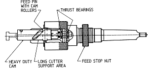
Figure 4: Recessing head using helical cam.
The first type of mechanism, an earlier design, involves the use of a helical cam or helical groove (Figure 4). The cutter is mounted off-center in a heavy-duty cam. As the head is compressed, a feed pin causes the cam to rotate, and the cutter feeds out eccentrically. Although the cutting geometry (i.e. rake angle) was constantly changing, toolmakers could make the tool work by grinding the desired angle on the cutter. Now, rather than shape the tool freehand on a grinder, toolmakers often use prepared cutters. Before the development of carbide inserts, however, the helical cam-type cutter provided a solution for dictating the angle at which the tool is presented to the workpiece.
Recessing vs. Circular Interpolation
Let’s consider a steel pump housing with a 3/4"-dia. bore requiring a groove 1/5" wide by 1/8" deep. We will use a standard HSS 1/2"-dia. milling cutter that is 1/8" wide with 6 teeth. We will run at a speed of 65 fpm and a feed of 0.0025 sfm per tooth.
S = maximum cutting speed (sfm)
D = hole diameter (inches)
d = depth of groove (inches)
DC = milling cutter diameter (inches)
N = number of flutes or teeth on milling cutter
f = maximum chipload on either cutter (inches)
To circular interpolate on a milling machine, the time to complete cutting of the groove is:
3.14 ² D DC / 12 f NS = 3.14 ² x 3/4 x 1/2 / 12 x 0.0025 x 6 x 65 = 0.31 min. = 19 sec.
Using an automatic recessing head, the time to complete cutting of the groove is:
3.14 ² d D / 12 f S = 3.14 ² x 1/8 x 3/4 / 12 x 0.0025 x 65 = 0.15 min. = 9 sec.
These formulas show that if there are enough parts to groove, recessing may be the most cost-effective method. In real applications, however, practical matters dominate. Let’s suppose the hole was 1/2" in diameter, the cutter was carbide, and the material was aluminum. We might not be able to run a recessing head at the nearly 3,000 rpm that would be permissible. Or, if the hole were 3" in diameter, we probably wouldn’t use a 2 3/4"-dia., 1/8"-wide cutter to circular interpolate.
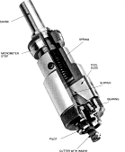
Figure 5: Recessing head with sliding-inclined-wedge construction.
Today, many users prefer a more contemporary mechanism design that involves the use of a sliding inclined wedge (Figure 5). The pilot and bearing are held in an outer body, which also accommodates the tool slide that holds the cutter. There is an inner body that straddles the tool slide and is able to move axially relative to the outer body when sufficient force is exerted to overcome the spring. An angular groove is cut in the tool slide into which a slipper is fitted. The slipper is attached to the inner body and moves axially with it.
When the inner body moves into the outer body, the slipper forces the tool slide and the cutter outward by wedge action. The angle of the groove in the tool slide determines the ratio of inner body downward motion to cutter radial motion. Typically designed to be a whole number for ease of setup, this feed ratio is usually between 2:1 and 5:1.
The sliding-inclined-wedge design ensures that the cutter retracts radially prior to axial withdrawal of the tool from the bore. This results in accurate control of groove depth. This mechanism design also results in a constant linear relationship between spindle movement and cutter movement. In addition, the straight-line movement of the cutter makes cutter regrinding easier.

Figure 6: Jig-plate recessing head (A) and rotating bushing (B).
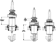
Figure 7: Operating principle of a jig-plate recessing head, including approach stroke (A), feed stroke (B), and end of feed stroke (C).
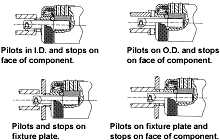
Figure 8: Four methods of piloting.
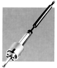
Figure 9: Automatic recessing head for multispindle automatics.
Today, many users prefer a more contemporary mechanism design that involves the use of a sliding inclined wedge (Figure 5). The pilot and bearing are held in an outer body, which also accommodates the tool slide that holds the cutter. There is an inner body that straddles the tool slide and is able to move axially relative to the outer body when sufficient force is exerted to overcome the spring. An angular groove is cut in the tool slide into which a slipper is fitted. The slipper is attached to the inner body and moves axially with it.
Head Designs
The pilots on the types of recessing heads discussed so far stop on the face of the component. Often, this is not possible due to the part configuration, or because it is undesirable to exert force on the part. In these applications, a jig-plate tool can be used (Figure 6). Rather than piloting off the workpiece, this type of recessing head operates off of a bearing, or rotating bushing, held in a jig plate above the part (Figure 7). Recessing heads are available in a variety of configurations to allow the user to locate and stop the tool on whatever surfaces are necessary (Figure 8).
During the approach stroke of a jig-plate tool on a drill press, for example, the head is rotating in the machine spindle and piloting in the bushing. The spindle is lowered. During the feed stroke, the adjustable stop collar bottoms against the face of the rotating bushing. Downward pressure causes compression of the recessing head, thereby actuating the slide mechanism that feeds the cutter out radially into the work. The correct DOC is obtained at the end of the feed stroke when the micrometer stop bottoms against the top of the outer body. Groove location is regulated by moving the adjustable stop collar up or down on the tool.
When using a jig-plate recessing head, it is necessary to hold the part rigidly in the fixture. Because it doesn’t pilot off the face of the workpiece, the jig-plate tool is suitable for cutting grooves on thin-walled parts that can’t withstand excessive force, and on parts where the face of the hole is on an angle.
Recessing heads also are available for use on multispindle automatics (Figure 9). The tool is generally mounted in a standard toolholder on the main tool slide and is fitted with a telescoping drawbar (Figure 10). The drawbar is attached to the wall of the gear box. As the main tool slide moves forward, carrying the recessing tool with it, the drawbar restrains the inner housing. Forward movement of the tool slide causes compression of the recessing head, thereby actuating the slide mechanism that feeds the cutter out radially into the work. The approximate DOC is primarily controlled by the movement of the main tool slide, which in turn, is fixed by its cam. Final DOC can be accurately adjusted by the nut on the drawbar.
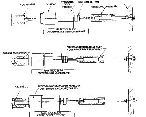
Figure 10: Operating principle of a multispindle recessing head, including approach stroke (A), feed stroke (B), and end of feed stroke (C).
A multispindle recessing head generally costs less than a ramp-type tool slide. Due to its compact design, the head will not interfere with other tooling on the main slide or cross slide. This type of head is suitable for back-chamfering prior to cutoff operations, and it eliminates secondary deburring operations.
The variety of automatic recessing heads available will suit most applications and machines. Besides being simple to set and operate, the heads ensure accuracy and repeatability, even when used by unskilled operators. Overall, these tools reduce cycle time and minimize costs, providing an economical option for precision grooving and recessing.
About the Author
Dr. William J. Westerman is president of Cogsdill Tool Products Inc., Camden, SC.
Related Glossary Terms
- boring
boring
Enlarging a hole that already has been drilled or cored. Generally, it is an operation of truing the previously drilled hole with a single-point, lathe-type tool. Boring is essentially internal turning, in that usually a single-point cutting tool forms the internal shape. Some tools are available with two cutting edges to balance cutting forces.
- boring bar
boring bar
Essentially a cantilever beam that holds one or more cutting tools in position during a boring operation. Can be held stationary and moved axially while the workpiece revolves around it, or revolved and moved axially while the workpiece is held stationary, or a combination of these actions. Installed on milling, drilling and boring machines, as well as lathes and machining centers.
- boring head
boring head
Single- or multiple-point precision tool used to bring an existing hole within dimensional tolerance. The head attaches to a standard toolholder and a mechanism permits fine adjustments to be made to the head within a diameter range.
- bushing
bushing
Cylindrical sleeve, typically made from high-grade tool steel, inserted into a jig fixture to guide cutting tools. There are three main types: renewable, used in liners that in turn are installed in the jig; press-fit, installed directly in the jig for short production runs; and liner (or master), installed permanently in a jig to receive renewable bushing.
- centers
centers
Cone-shaped pins that support a workpiece by one or two ends during machining. The centers fit into holes drilled in the workpiece ends. Centers that turn with the workpiece are called “live” centers; those that do not are called “dead” centers.
- computer numerical control ( CNC)
computer numerical control ( CNC)
Microprocessor-based controller dedicated to a machine tool that permits the creation or modification of parts. Programmed numerical control activates the machine’s servos and spindle drives and controls the various machining operations. See DNC, direct numerical control; NC, numerical control.
- computer-aided manufacturing ( CAM)
computer-aided manufacturing ( CAM)
Use of computers to control machining and manufacturing processes.
- cutoff
cutoff
Step that prepares a slug, blank or other workpiece for machining or other processing by separating it from the original stock. Performed on lathes, chucking machines, automatic screw machines and other turning machines. Also performed on milling machines, machining centers with slitting saws and sawing machines with cold (circular) saws, hacksaws, bandsaws or abrasive cutoff saws. See saw, sawing machine; turning.
- cutting speed
cutting speed
Tangential velocity on the surface of the tool or workpiece at the cutting interface. The formula for cutting speed (sfm) is tool diameter 5 0.26 5 spindle speed (rpm). The formula for feed per tooth (fpt) is table feed (ipm)/number of flutes/spindle speed (rpm). The formula for spindle speed (rpm) is cutting speed (sfm) 5 3.82/tool diameter. The formula for table feed (ipm) is feed per tooth (ftp) 5 number of tool flutes 5 spindle speed (rpm).
- depth of cut
depth of cut
Distance between the bottom of the cut and the uncut surface of the workpiece, measured in a direction at right angles to the machined surface of the workpiece.
- drilling machine ( drill press)
drilling machine ( drill press)
Machine designed to rotate end-cutting tools. Can also be used for reaming, tapping, countersinking, counterboring, spotfacing and boring.
- feed
feed
Rate of change of position of the tool as a whole, relative to the workpiece while cutting.
- fixture
fixture
Device, often made in-house, that holds a specific workpiece. See jig; modular fixturing.
- flutes
flutes
Grooves and spaces in the body of a tool that permit chip removal from, and cutting-fluid application to, the point of cut.
- gang cutting ( milling)
gang cutting ( milling)
Machining with several cutters mounted on a single arbor, generally for simultaneous cutting.
- grinding
grinding
Machining operation in which material is removed from the workpiece by a powered abrasive wheel, stone, belt, paste, sheet, compound, slurry, etc. Takes various forms: surface grinding (creates flat and/or squared surfaces); cylindrical grinding (for external cylindrical and tapered shapes, fillets, undercuts, etc.); centerless grinding; chamfering; thread and form grinding; tool and cutter grinding; offhand grinding; lapping and polishing (grinding with extremely fine grits to create ultrasmooth surfaces); honing; and disc grinding.
- grooving
grooving
Machining grooves and shallow channels. Example: grooving ball-bearing raceways. Typically performed by tools that are capable of light cuts at high feed rates. Imparts high-quality finish.
- high-speed steels ( HSS)
high-speed steels ( HSS)
Available in two major types: tungsten high-speed steels (designated by letter T having tungsten as the principal alloying element) and molybdenum high-speed steels (designated by letter M having molybdenum as the principal alloying element). The type T high-speed steels containing cobalt have higher wear resistance and greater red (hot) hardness, withstanding cutting temperature up to 1,100º F (590º C). The type T steels are used to fabricate metalcutting tools (milling cutters, drills, reamers and taps), woodworking tools, various types of punches and dies, ball and roller bearings. The type M steels are used for cutting tools and various types of dies.
- interpolation
interpolation
Process of generating a sufficient number of positioning commands for the servomotors driving the machine tool so the path of the tool closely approximates the ideal path. See CNC, computer numerical control; NC, numerical control.
- jig
jig
Tooling usually considered to be a stationary apparatus. A jig assists in the assembly or manufacture of a part or device. It holds the workpiece while guiding the cutting tool with a bushing. A jig used in subassembly or final assembly might provide assembly aids such as alignments and adjustments. See fixture.
- lathe
lathe
Turning machine capable of sawing, milling, grinding, gear-cutting, drilling, reaming, boring, threading, facing, chamfering, grooving, knurling, spinning, parting, necking, taper-cutting, and cam- and eccentric-cutting, as well as step- and straight-turning. Comes in a variety of forms, ranging from manual to semiautomatic to fully automatic, with major types being engine lathes, turning and contouring lathes, turret lathes and numerical-control lathes. The engine lathe consists of a headstock and spindle, tailstock, bed, carriage (complete with apron) and cross slides. Features include gear- (speed) and feed-selector levers, toolpost, compound rest, lead screw and reversing lead screw, threading dial and rapid-traverse lever. Special lathe types include through-the-spindle, camshaft and crankshaft, brake drum and rotor, spinning and gun-barrel machines. Toolroom and bench lathes are used for precision work; the former for tool-and-die work and similar tasks, the latter for small workpieces (instruments, watches), normally without a power feed. Models are typically designated according to their “swing,” or the largest-diameter workpiece that can be rotated; bed length, or the distance between centers; and horsepower generated. See turning machine.
- metalworking
metalworking
Any manufacturing process in which metal is processed or machined such that the workpiece is given a new shape. Broadly defined, the term includes processes such as design and layout, heat-treating, material handling and inspection.
- micrometer
micrometer
A precision instrument with a spindle moved by a finely threaded screw that is used for measuring thickness and short lengths.
- milling
milling
Machining operation in which metal or other material is removed by applying power to a rotating cutter. In vertical milling, the cutting tool is mounted vertically on the spindle. In horizontal milling, the cutting tool is mounted horizontally, either directly on the spindle or on an arbor. Horizontal milling is further broken down into conventional milling, where the cutter rotates opposite the direction of feed, or “up” into the workpiece; and climb milling, where the cutter rotates in the direction of feed, or “down” into the workpiece. Milling operations include plane or surface milling, endmilling, facemilling, angle milling, form milling and profiling.
- milling cutter
milling cutter
Loosely, any milling tool. Horizontal cutters take the form of plain milling cutters, plain spiral-tooth cutters, helical cutters, side-milling cutters, staggered-tooth side-milling cutters, facemilling cutters, angular cutters, double-angle cutters, convex and concave form-milling cutters, straddle-sprocket cutters, spur-gear cutters, corner-rounding cutters and slitting saws. Vertical cutters use shank-mounted cutting tools, including endmills, T-slot cutters, Woodruff keyseat cutters and dovetail cutters; these may also be used on horizontal mills. See milling.
- milling machine ( mill)
milling machine ( mill)
Runs endmills and arbor-mounted milling cutters. Features include a head with a spindle that drives the cutters; a column, knee and table that provide motion in the three Cartesian axes; and a base that supports the components and houses the cutting-fluid pump and reservoir. The work is mounted on the table and fed into the rotating cutter or endmill to accomplish the milling steps; vertical milling machines also feed endmills into the work by means of a spindle-mounted quill. Models range from small manual machines to big bed-type and duplex mills. All take one of three basic forms: vertical, horizontal or convertible horizontal/vertical. Vertical machines may be knee-type (the table is mounted on a knee that can be elevated) or bed-type (the table is securely supported and only moves horizontally). In general, horizontal machines are bigger and more powerful, while vertical machines are lighter but more versatile and easier to set up and operate.
- milling machine ( mill)2
milling machine ( mill)
Runs endmills and arbor-mounted milling cutters. Features include a head with a spindle that drives the cutters; a column, knee and table that provide motion in the three Cartesian axes; and a base that supports the components and houses the cutting-fluid pump and reservoir. The work is mounted on the table and fed into the rotating cutter or endmill to accomplish the milling steps; vertical milling machines also feed endmills into the work by means of a spindle-mounted quill. Models range from small manual machines to big bed-type and duplex mills. All take one of three basic forms: vertical, horizontal or convertible horizontal/vertical. Vertical machines may be knee-type (the table is mounted on a knee that can be elevated) or bed-type (the table is securely supported and only moves horizontally). In general, horizontal machines are bigger and more powerful, while vertical machines are lighter but more versatile and easier to set up and operate.
- rake
rake
Angle of inclination between the face of the cutting tool and the workpiece. If the face of the tool lies in a plane through the axis of the workpiece, the tool is said to have a neutral, or zero, rake. If the inclination of the tool face makes the cutting edge more acute than when the rake angle is zero, the rake is positive. If the inclination of the tool face makes the cutting edge less acute or more blunt than when the rake angle is zero, the rake is negative.
- recessing
recessing
A turning operation in which a groove is produced on the periphery or inside a hole of a workpiece. The grooving tool moves at right angles to the axis of rotation.
- shank
shank
Main body of a tool; the portion of a drill or similar end-held tool that fits into a collet, chuck or similar mounting device.
- toolholder
toolholder
Secures a cutting tool during a machining operation. Basic types include block, cartridge, chuck, collet, fixed, modular, quick-change and rotating.
- turning
turning
Workpiece is held in a chuck, mounted on a face plate or secured between centers and rotated while a cutting tool, normally a single-point tool, is fed into it along its periphery or across its end or face. Takes the form of straight turning (cutting along the periphery of the workpiece); taper turning (creating a taper); step turning (turning different-size diameters on the same work); chamfering (beveling an edge or shoulder); facing (cutting on an end); turning threads (usually external but can be internal); roughing (high-volume metal removal); and finishing (final light cuts). Performed on lathes, turning centers, chucking machines, automatic screw machines and similar machines.
- undercut
undercut
In numerical-control applications, a cut shorter than the programmed cut resulting after a command change in direction. Also a condition in generated gear teeth when any part of the fillet curve lies inside of a line drawn tangent to the working profile at its point of juncture with the fillet. Undercut may be deliberately introduced to facilitate finishing operations, as in preshaving.
