


Over my career I’ve made thousands of different parts for a manufacturer of industrial and military machines. The volumes were usually in the single digits.
While I consider myself an expert in small-lot precision machining, high-volume part production is another matter. While working on my thread milling articles for this column, I met an EMUGE-FRANKEN USA engineer who is an expert on high-volume production.
Before writing last month’s “Intro to Thread Milling,” I did not think a thread mill existed that cut perfect threads. Years ago, I used thread mills to make parts. The threads had concave flanks. That is OK for many applications, but it can cause trouble if the application has a high load factor.
I have learned that EMUGE makes tools that cut perfect V threads. If you missed last month’s column, and you are interested in thread milling, you should read it. EMUGE’s thread mills have a flat at the point of the V. Each mill is made for a small range of threads. This means there is a little more axial backlash with a loose bolt in the hole, but when the bolt is tightened the assembly is precise. EMUGE makes plug gauges for testing the cut threads.
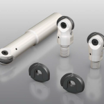
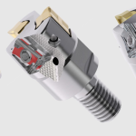
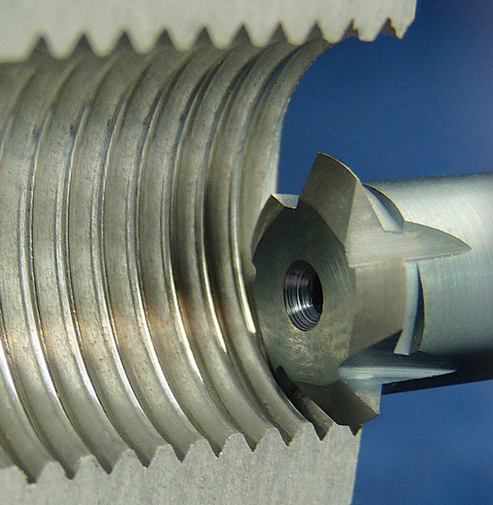
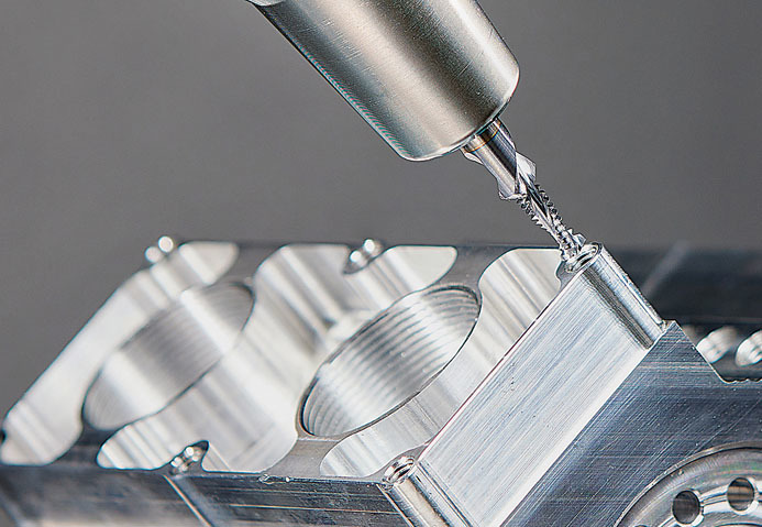
Figure 1 shows a single-plane tool in a cutaway thread. Figure 2 shows a multi-plane tool called Thriller. The company also makes tools that will drill and thread a hole in a single pass. I will be writing about those tools in a future article.
Deeper dive
For this report, I dove deeper into EMUGE’s thread milling products. They have features that are unique. EMUGE uses sophisticated grinding operations to reduce the clearance angle on the cutting edges. This produces better edge strength, which makes for longer tool life. Also, the company offers resharpening and recoating services for thread mills in Germany and offer these same services for their drills, taps and endmills in the U.S. And, if a customer needs a longer length of cut (LOC) than can be made with a standard tool, EMUGE can make the neck of the tool longer for that longer LOC. This is done here in the U.S.
Climb or conventional milling
Climb milling or conventional milling both have advantages and disadvantages. With climb milling there is a greater tendency for the tool to chatter so feeds and speeds often need to be less than those used in conventional milling. On the other hand, with conventional milling, the cutting edges rub when entering the cut so tool life is less.
I prefer climb milling as I have found I get better part quality and consistency, and, because of my low-volume situation, the longer cycle time is not an issue. EMUGE has data and recommendations for whatever volume you need to tackle.
Speeds and feeds
Now to feeds and speeds. Like other carbide tools, cutting speeds are 200 to 600 feet per minute depending on the workpiece material and machining conditions. My bible for speeds and feeds is the Machinery’s Handbook, which provides such data through a host of tables. EMUGE also has tables and knowledgeable people to assist you.
Remember, the temperature of the cutting edge influences tool life greatly. Keep it cool. Chip load on the cutting edge with cutting speed determines feed rate. A good place to start is 0.0005" to 0.0012" per tooth. Cutting a thread with two passes is a safe bet. Cut 70% of the depth of cut with the first pass and 100% with the finish pass.
Where to start?
When doing thread milling, I like to start the cut at the deepest tool position in the hole and cut while retracting the tool. With a right-handed thread this will produce climb milling. This way, if the tool breaks or something else goes wrong, it is less likely to cause a damaged workpiece.
Here is a programing example for using an EMUGE Thriller to cut a 1/2-20 thread, 0.60" deep. This program uses polar coordinates to cut the thread in two revolutions of a helical tool path. The first revolution is at 70% of the depth of cut, and the second revolution at 100% finishes the thread. The center of the hole is at X4.Y3.Z0.
N1T20M06
N10S1200M03
N20G90G15G0X4.Y3.Z.1
N30G1Z-.6F100
N40G16G1R0.056A90I4.J3.F40
=N50/500
N50G91A-.72Z.0001F40
N60G15G1G90X4.Y3.F100
N70Z-.6
N80G16G1R.063A90I4.J3.F40
=N90/500
N90GG91G1A-.72Z.0001F40
N100G15G1G90X4.Y3.F100
N110G0Z.1
N120M02
It seems to be easier for me to find bugs in helical programs using polar coordinates. It’s nice for doing bolt circles too.
I have always found it more fun to make money than to make scrap.
Related Glossary Terms
- backlash
backlash
Reaction in dynamic motion systems where potential energy that was created while the object was in motion is released when the object stops. Release of this potential energy or inertia causes the device to quickly snap backward relative to the last direction of motion. Backlash can cause a system’s final resting position to be different from what was intended and from where the control system intended to stop the device.
- chatter
chatter
Condition of vibration involving the machine, workpiece and cutting tool. Once this condition arises, it is often self-sustaining until the problem is corrected. Chatter can be identified when lines or grooves appear at regular intervals in the workpiece. These lines or grooves are caused by the teeth of the cutter as they vibrate in and out of the workpiece and their spacing depends on the frequency of vibration.
- clearance
clearance
Space provided behind a tool’s land or relief to prevent rubbing and subsequent premature deterioration of the tool. See land; relief.
- climb milling ( down milling)
climb milling ( down milling)
Rotation of a milling tool in the same direction as the feed at the point of contact. Chips are cut to maximum thickness at the initial engagement of the cutter’s teeth with the workpiece and decrease in thickness at the end of engagement. See conventional milling.
- conventional milling ( up milling)
conventional milling ( up milling)
Cutter rotation is opposite that of the feed at the point of contact. Chips are cut at minimal thickness at the initial engagement of the cutter’s teeth with the workpiece and increase to a maximum thickness at the end of engagement. See climb milling.
- cutting speed
cutting speed
Tangential velocity on the surface of the tool or workpiece at the cutting interface. The formula for cutting speed (sfm) is tool diameter 5 0.26 5 spindle speed (rpm). The formula for feed per tooth (fpt) is table feed (ipm)/number of flutes/spindle speed (rpm). The formula for spindle speed (rpm) is cutting speed (sfm) 5 3.82/tool diameter. The formula for table feed (ipm) is feed per tooth (ftp) 5 number of tool flutes 5 spindle speed (rpm).
- depth of cut
depth of cut
Distance between the bottom of the cut and the uncut surface of the workpiece, measured in a direction at right angles to the machined surface of the workpiece.
- feed
feed
Rate of change of position of the tool as a whole, relative to the workpiece while cutting.
- flat ( screw flat)
flat ( screw flat)
Flat surface machined into the shank of a cutting tool for enhanced holding of the tool.
- gang cutting ( milling)
gang cutting ( milling)
Machining with several cutters mounted on a single arbor, generally for simultaneous cutting.
- grinding
grinding
Machining operation in which material is removed from the workpiece by a powered abrasive wheel, stone, belt, paste, sheet, compound, slurry, etc. Takes various forms: surface grinding (creates flat and/or squared surfaces); cylindrical grinding (for external cylindrical and tapered shapes, fillets, undercuts, etc.); centerless grinding; chamfering; thread and form grinding; tool and cutter grinding; offhand grinding; lapping and polishing (grinding with extremely fine grits to create ultrasmooth surfaces); honing; and disc grinding.
- milling
milling
Machining operation in which metal or other material is removed by applying power to a rotating cutter. In vertical milling, the cutting tool is mounted vertically on the spindle. In horizontal milling, the cutting tool is mounted horizontally, either directly on the spindle or on an arbor. Horizontal milling is further broken down into conventional milling, where the cutter rotates opposite the direction of feed, or “up” into the workpiece; and climb milling, where the cutter rotates in the direction of feed, or “down” into the workpiece. Milling operations include plane or surface milling, endmilling, facemilling, angle milling, form milling and profiling.
- milling machine ( mill)
milling machine ( mill)
Runs endmills and arbor-mounted milling cutters. Features include a head with a spindle that drives the cutters; a column, knee and table that provide motion in the three Cartesian axes; and a base that supports the components and houses the cutting-fluid pump and reservoir. The work is mounted on the table and fed into the rotating cutter or endmill to accomplish the milling steps; vertical milling machines also feed endmills into the work by means of a spindle-mounted quill. Models range from small manual machines to big bed-type and duplex mills. All take one of three basic forms: vertical, horizontal or convertible horizontal/vertical. Vertical machines may be knee-type (the table is mounted on a knee that can be elevated) or bed-type (the table is securely supported and only moves horizontally). In general, horizontal machines are bigger and more powerful, while vertical machines are lighter but more versatile and easier to set up and operate.
- precision machining ( precision measurement)
precision machining ( precision measurement)
Machining and measuring to exacting standards. Four basic considerations are: dimensions, or geometrical characteristics such as lengths, angles and diameters of which the sizes are numerically specified; limits, or the maximum and minimum sizes permissible for a specified dimension; tolerances, or the total permissible variations in size; and allowances, or the prescribed differences in dimensions between mating parts.