Contact Details
Kennametal's new asymmetric line-boring solution increases machining robustness, process speeds, and bore quality, and reduces tool maintenance and handling.
Precision boring is a vital process in manufacturing many critical components. The accuracy and finish of a multi-journal crank bore in an engine block relates directly to power and fuel efficiency, and the time it takes relates directly to the engine company's profits. Precision bores in numerous engineered components are essential to critical performance metrics. Such bores must meet critical tolerances; but the downside is that precision boring can be costly and time-consuming, with a small mistake or error resulting in the scrapping of expensive parts. The response from Kennametal is a geometric and asymmetric line boring bar solution being termed a revolution in the process by delighted users.
By definition, boring, as opposed to drilling, is a machining process in which internal diameters are made in true relation to the spindle centerline. This process is most commonly performed with the workpiece held stationary and the cutting tool both rotating and advancing into the workpiece, although boring is also done with the cutting tool and the workpiece being adjustable.
Common applications for boring include the enlarging or finishing of cored, pierced, or drilled holes and contoured internal surfaces. Related operations sometimes performed simultaneously with boring include turning, facing, chamfering, grooving, and threading.
Envision a small engine block with five in-line journals requiring crank bores. Conventional thinking for a multi-journal finishing assignment, for example, involves a multi-blade guidepad reamer with the following suggested process (here designated as Option 1.0):
• A pilot reamer finishes the first journal
• The multi-blade reamer is fed in and semi- and final-finishes journals 2 through 5.
• The reamer is then retracted.
The advantage of such a process is that it lends itself to use on CNC horizontal or multi-axis machining centers and does not require a dedicated boring machine with dedicated fixtures. However, depending on the size of the workpiece, the machine tool must be of sufficient rigidity or quality can fall off dramatically. Also, feed-in and feed-out of the reaming tool over finished bores must be done slowly and precisely or retraction marks and/or damage to the cutting edges will occur.
Another general option for machining this kind of bore is line boring (Option 2.0). The basic issue to be solved at this option is how can the cutting blades and the tool's guide pads pass through unfinished journals with smaller hole diameters?
CNC machine tool builders have responded to this quandary with using conventional line boring bars and "counter-bearing" capabilities on their equipment. The process looks like the following:
• The workpiece area of the machine tool lifts the cylinder block up
• The line boring bar is fed through the component into a bearing at the opposite end
• The cylinder block is adjusted down and clamped
• Crank bores are semi- and final-finished
• The cylinder block is lifted up and the boring bar retracted
The process speeds up feed-in and feed-out, and because the tool is supported on both ends; the geometric quality of the finished bore is improved compared to reaming option 1.0. On the downside, lift functions require special fixturing and CNC control, and the required counter-bearing on the fixture makes any additional back-side machining impossible.
Multi-axis machine tools with tilting worktables and/or tilting spindles together with more evolved boring bars contribute to Line Boring Option 2.1 with expandable guide pads, where the process evolves to the following:
• A pilot reamer is fed in and finishes journal 5
• The component (or machine table) gets rotated 180 degrees
• The machining center X-Y axis is adjusted to feed the boring bar in off-center
• The boring bar with guide pads is centered into journal 5
• Guide pads are expanded
• Journals 1 through 4 are semi- and final-finished
• Guide pads are fed back in
• The boring bar is retracted off-center
Option 2.1 uses the multi-axis adjustability of the machine tool. It retains the advantages of Option 1.0 by eliminating the need for any lift function or counterbearing and Option 2.0 with support on both ends of the tool. The disadvantages are that the complex internal mechanics of this type of boring bar are costly and can be difficult to handle. Insufficient lubrication use can damage sensitive internal mechanics, and if not monitored exactly, the tool can jam or hook in the workpiece and cause damage to the machine, fixture, tool and part.
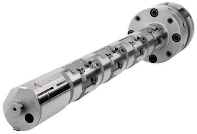
In collaboration with a major automotive manufacturer's engine block operations, Kennametal engineering staff has advanced the boring function with Option3.0, asymmetric line boring. This is a geometric leap forward that accentuates the advantages of reaming and line boring while virtually eliminating the disadvantages of both.
As with most advanced solutions, the principle at the foundation is quite basic. Normal guide diameters are of full material or build of 3 or more guide pads, providing no degree of freedom from the bore wall while feeding in and out. The Kennametal solution supports on guide pads in a setup similar to a typical guide pad reamer, but the guide pad, normally located 180° to the cutting edge, was rotated so the resulting design provides freedom to enter and exit the guide part even passing through the raw bores. This geometry allows feeding the bar through raw bores on an eccentric path. The process, then, looks like this:
• A pilot reamer is fed in and finishes journal 5
• The component (or machine table) gets rotated 180 degrees
• The asymmetric boring bar is fed in off-center using the machining center's X-Y axis
• The tool is moved to the center and finishes journals 1 through 4 simultaneously
• The tool is retracted off-center with fast feed out.
Such asymmetric line boring retains all the advantages of previous line boring efforts--high-quality precision bores, support on both ends of the tool, while no expensive lift functions, obstructive counter bearings or critical mechanisms inside the tool are needed. It also adds the fact that complete feed-in and feed-out moves can be done at increased feed rates on conventional machining centers, adding efficiency to the process.
Naturally, being a Kennametal solution, the indexable inserts offered with this eccentric boring bar solution are also advanced. High-precision RI8 inserts have eight cutting edges with pre-defined back taper, which allows for high feed rates. Diameter can be adjusted to the precision of 1µm. The high clamping force provided by the conical clamp screw avoids any settling effects.
Both inserts and the asymmetric boring bar are designed so the inserts clamp directly into the boring bar body. This eliminates the need for cartridges and the additional tolerances and space they require. In short, this asymmetric line-boring solution increases machining robustness, process speeds, and reduces tool maintenance and handling, all while being compatible with CNC machining centers, a solution any manufacturer in search of process improvements will find anything but boring.
Related Glossary Terms
- boring
boring
Enlarging a hole that already has been drilled or cored. Generally, it is an operation of truing the previously drilled hole with a single-point, lathe-type tool. Boring is essentially internal turning, in that usually a single-point cutting tool forms the internal shape. Some tools are available with two cutting edges to balance cutting forces.
- boring bar
boring bar
Essentially a cantilever beam that holds one or more cutting tools in position during a boring operation. Can be held stationary and moved axially while the workpiece revolves around it, or revolved and moved axially while the workpiece is held stationary, or a combination of these actions. Installed on milling, drilling and boring machines, as well as lathes and machining centers.
- boring machine
boring machine
Similar to a turning machine except that the cutting tool (single-point or multiple-cutting-edge), rather than the workpiece, rotates to perform internal cuts. However, boring can be accomplished by holding the tool stationary and turning the workpiece. Takes a variety of vertical, slanted and horizontal forms, and has one or more spindles. Typically a large, powerful machine, it can readily hold tolerances to 0.0001". See jig boring; lathe; turning machine.
- centers
centers
Cone-shaped pins that support a workpiece by one or two ends during machining. The centers fit into holes drilled in the workpiece ends. Centers that turn with the workpiece are called “live” centers; those that do not are called “dead” centers.
- chamfering
chamfering
Machining a bevel on a workpiece or tool; improves a tool’s entrance into the cut.
- computer numerical control ( CNC)
computer numerical control ( CNC)
Microprocessor-based controller dedicated to a machine tool that permits the creation or modification of parts. Programmed numerical control activates the machine’s servos and spindle drives and controls the various machining operations. See DNC, direct numerical control; NC, numerical control.
- feed
feed
Rate of change of position of the tool as a whole, relative to the workpiece while cutting.
- fixture
fixture
Device, often made in-house, that holds a specific workpiece. See jig; modular fixturing.
- grooving
grooving
Machining grooves and shallow channels. Example: grooving ball-bearing raceways. Typically performed by tools that are capable of light cuts at high feed rates. Imparts high-quality finish.
- machining center
machining center
CNC machine tool capable of drilling, reaming, tapping, milling and boring. Normally comes with an automatic toolchanger. See automatic toolchanger.
- reamer
reamer
Rotating cutting tool used to enlarge a drilled hole to size. Normally removes only a small amount of stock. The workpiece supports the multiple-edge cutting tool. Also for contouring an existing hole.
- threading
threading
Process of both external (e.g., thread milling) and internal (e.g., tapping, thread milling) cutting, turning and rolling of threads into particular material. Standardized specifications are available to determine the desired results of the threading process. Numerous thread-series designations are written for specific applications. Threading often is performed on a lathe. Specifications such as thread height are critical in determining the strength of the threads. The material used is taken into consideration in determining the expected results of any particular application for that threaded piece. In external threading, a calculated depth is required as well as a particular angle to the cut. To perform internal threading, the exact diameter to bore the hole is critical before threading. The threads are distinguished from one another by the amount of tolerance and/or allowance that is specified. See turning.
- turning
turning
Workpiece is held in a chuck, mounted on a face plate or secured between centers and rotated while a cutting tool, normally a single-point tool, is fed into it along its periphery or across its end or face. Takes the form of straight turning (cutting along the periphery of the workpiece); taper turning (creating a taper); step turning (turning different-size diameters on the same work); chamfering (beveling an edge or shoulder); facing (cutting on an end); turning threads (usually external but can be internal); roughing (high-volume metal removal); and finishing (final light cuts). Performed on lathes, turning centers, chucking machines, automatic screw machines and similar machines.