The ins and outs of machine tool spindle maintenance
A robust spindle maintenance plan helps avoid unexpected repair bills and days or even weeks of downtime.
The control is the brain, the servomotors the muscle, but the spindle is the heart of any CNC machine tool. Just as with humans, machining centers need a dependable heart to avoid tragedy. For machine shops, that tragedy manifests itself as unexpected repair bills and days or even weeks of downtime.
Customer deliveries and cash flow alike are affected when a spindle seizes; cutters break, parts are scrapped, and operators may be injured. Fortunately, a robust machine spindle preventive maintenance plan helps avoid all this unpleasantness.
More often than not, poor air supply to spindles is a significant factor in premature machine tool spindle failures. Image courtesy of GTI Spindle Technology
Best Practices
Each spindle builder who contributed to this article offered much the same advice: Keep machine tools and spindles clean, don’t put off repairs until the shop is less busy, and follow sound machining practices.
- Kill contamination. No one should be expected to breathe dirty air, and this is just as true for machine tools as for machinists. If a shop’s compressor routinely spits out watery or oily air, rest assured that air will work its way into your machine tool’s critical components, including air-purged spindle bearings. Keep the water trap on the machine’s compressed air regulator clean. If it has an oil reservoir attached (most do), check it daily. Remember that air compressors also need routine maintenance.
- Ease into it. Any automaker would advise against taking a new sports car to a racetrack or pulling stumps with a new pickup without first “breaking it in.” Machine tool spindles are no different. Always follow the manufacturer’s recommendations on spindle startup. Even veteran machine tools should be given a chance to ease into production, especially after a long weekend. After turning on the machine, bring up the spindle to a couple of thousand rpm, grab a cup of coffee and spend a few minutes planning your day while the machine warms up.
- Use the force. When the Belleville washers found in most machining center drawbars fatigue, their grip on toolholders within the spindle taper becomes less secure. Microscopic holder movement ensues, hurting part quality and tool life and most likely damaging the spindle and toolholders as well. The solution is a drawbar force meter, which allows operators to quickly inspect this often overlooked machine component. Although a meter can cost $1,000 or more, the investment may mean avoiding damage to a spindle that could easily cost 10 times that amount to repair.
- Buy top-grade tooling. A high-quality, well-maintained toolholder is another overlooked component of successful machining. Inspect and clean toolholders and the spindle every day. If toolholder tapers have fretting, chip marks or rust, replace them. Use high-quality retention knobs; recognize that they and the toolholders have a life span of roughly 6,000 hours under normal use. Balance all toolholder assemblies that operate at 8,000 rpm or higher. Finally, minimize the radial cutting forces and amount of tool overhang—applying a cutter that’s sticking out 10 diameters deep to hog a deep pocket is asking for trouble.
- Don’t wait. Repairing spindles sooner rather than later means avoiding the catastrophic damage that occurs when bearings seize. Instead of performing a simple, less expensive rebuild at a time of your choosing, the spindle will need to be shipped in the quickest possible manner. The spindle builder will likely charge expedited fees for services. Shafts will need to be reground or even replaced, as will damaged spindle housings and other components, further increasing repair time and costs.
These are all great recommendations, but the sad truth is that, no matter how vigorous the maintenance strategy or faithful its application, stuff happens. “Today’s machine tools are incredibly complex and becoming more so all the time,” said Claude Valenze, general manager at High Speed Technologies Inc., Candia, New Hampshire. “Because of this, programming or setup mistakes are very easy to make and often result in a machine crash. For us, this is the most common reason for spindle repair.”
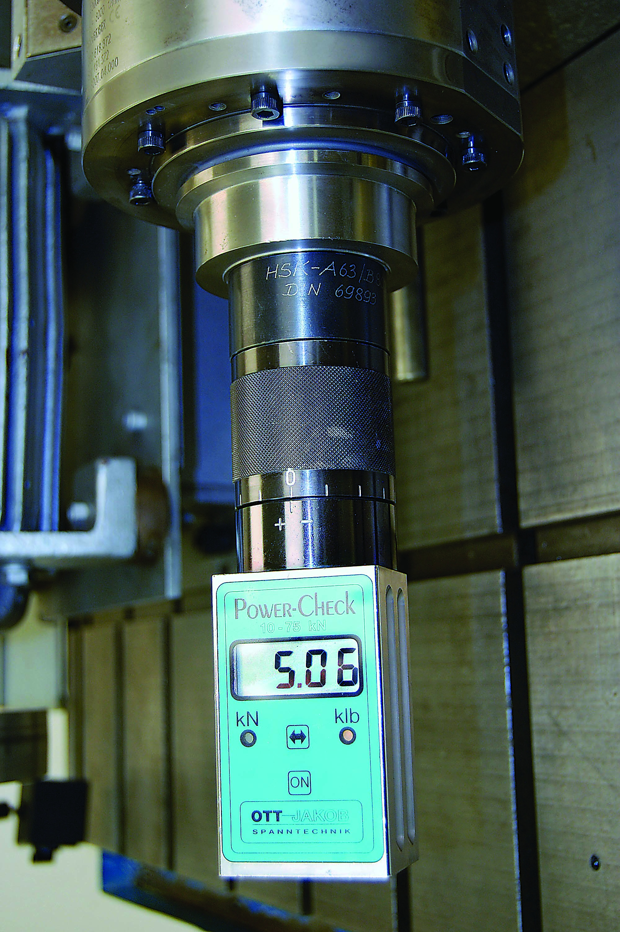
Routinely checking the drawbar pull force is an important part of any machining center maintenance routine. Image courtesy of High Speed Technologies
Simulate and Stay Dry
Valenze said toolpath simulation is a top way to avoid crashes. To help avoid future ones, he advises to watch where coolant goes.
“Any spindle running faster than 3,000 rpm uses labyrinth seals, which do not make direct contact with the spindle shaft,” he said. “If cutting fluid is sprayed directly at this seal, it can bounce up inside the bearings, eventually destroying them.”
Valenze explained that machine builders compensate for this with positive air pressure inside the spindle housing, using what’s called an air knife or air curtain. “This is usually effective,” he added, “but it’s still a good idea to direct cutting fluids down and away from the spindle face. Also, allow the spindle to run for a few seconds at the end of each machine cycle with the coolant turned off.”
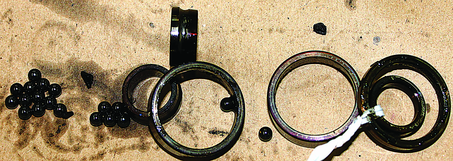
Don Loveless, sales manager at GMN USA LLC, Bristol, Connecticut, sees similar spindle scenarios. “Crashes are No. 1, but coolant contamination is also quite common,” he said. “The labyrinth seals tend to draw coolant up into the bearings, which is why you always want to make sure the air purge is functioning properly and that you have clean, dry air going in.”
As mentioned earlier, improper tool application is another routine mistake. All machine spindles are rated for a certain mass. When using tools that are too large, too long or out of balance, premature spindle failure is bound to occur.
“It’s usually the rear bearing that goes as that’s what takes most of the load in this situation,” Loveless explained. “When in doubt over what’s too big or too heavy, call us or check with your machine tool builder. We’ll be happy to do the calculation for you.”
Repair Time
Assuming that your shop follows this article’s recommendations, there’s a good chance of being able to replace spindle bearings yourself—Valenze even offers a multipart tutorial on his blog at www.highspeedtechnologies.com/blog. But for shops that would rather focus on making parts or in situations where a spindle is damaged to the point that grinding is necessary, send it to a company that specializes in spindle repair.
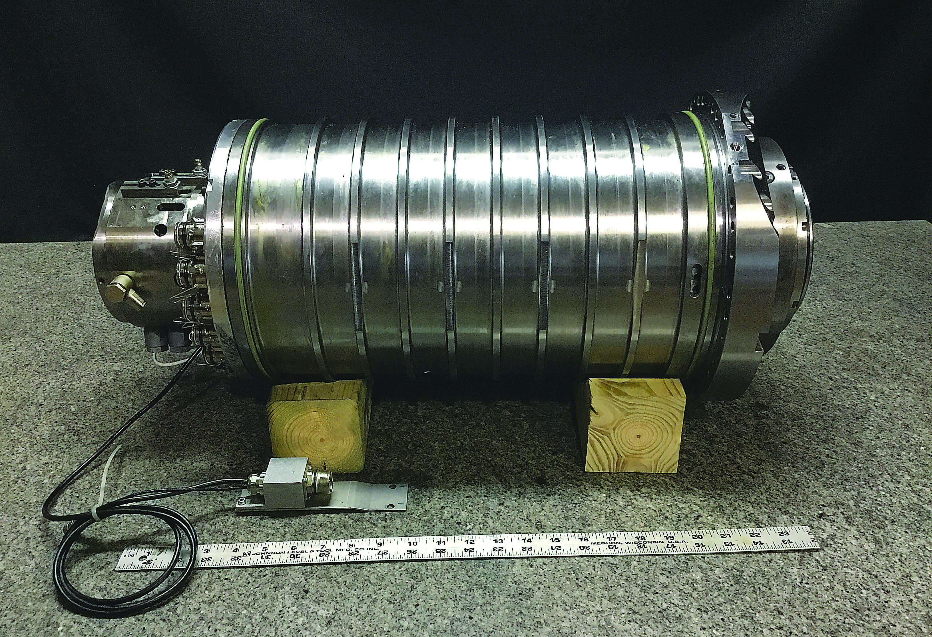
A newly rebuilt spindle, ready for installation at a customer’s facility. Image courtesy of Motor City Spindle Repair
Motor City Spindle Repair Inc., Dearborn, Michigan, is one such company. Owner and Vice President Brian Burns agrees that many shops can perform basic spindle rebuilds, especially shops with less demanding work. However, he noted, bringing the spindle back to factory specifications—remanufacturing it, in other words—is the most cost-effective, dependable solution for most machine shops.
“That’s one of the main reasons why we moved recently into a bigger facility, so we could bring all the stuff we were once outsourcing back under our direct control,” Burns said. “That means the grinding, the machining and so on—whatever’s needed to make spindles like new again.”
The move has also helped the Motor City team promote one of its products, a machine tool monitoring system from Italian company Balance Systems SRL. Burns said installing such a system “basically turns a CNC into a smart machine,” allowing users to monitor spindle temperature, vibration, cutting forces and more. “There’s even a setting that shuts the machine down if there’s a crash or other problem, so you can avoid having to send your spindle to us in the first place,” he said.
Review the print ads from this magazine to continue
This quick advertiser review unlocks the rest of the article and keeps the full-screen reader focused on the ads instead of the page chrome.

