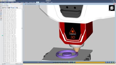
In VERICUT 8.1 from CGTech, a new additive manufacturing (AM) module has been employed, along with enhanced support for Force optimization, workpiece sectioning, X-Caliper measurement tool, report template, and grinding and dressing operations.
VERICUT’s additive module simulates both additive and traditional machining capabilities used in any order on hybrid CNC machines. Simulating both operations can identify potential problems that can occur when integrating additive methods. The user can access detailed “history” stored with VERICUT’s unique droplet technology, which saves programmers time by quickly identifying the source of errors, in most cases using a single mouse-click.
This additive capability checks: accurate laser cladding and material deposition, detects collisions between the machine and additive part, and finds errors, voids, and misplaced material. For the highest accuracy, VERICUT simulates the post-processed NC code that will be used to drive the CNC machine, and ensures proper usage of AM functions and laser parameters. Users can virtually experiment with combining additive and metal removal processes to determine optimal safe hybrid manufacturing methods.
“Additive manufacturing applications create new possibilities for manufacturers,” said Gene Granata, VERICUT product manager. “Adding this technology to VERICUT provides unique solutions that address the needs of our customers in the rapidly expanding AM market.”
VERICUT’s Force optimizes NC programs by analyzing cutting conditions such as force, chip thickness and feed rate. In 8.1, Force can display graphs and charts in real-time, revealing cutting conditions and forces as they are encountered by cutting tools. This feature allows the NC programmer to identify undesirable cutting conditions, such as excessive forces, chip loads, tool deflection, or material removal rates represented as spikes in the graphs. Force Charts are dynamically linked with VERICUT’s NC Program Review, making it easy to review problem cutting conditions. With one click on the chart, the user is taken to the location in the CNC program and shown the actual cut in the graphics window. By optimizing toolpath feed rates: Force reduces production time, prolongs tool life, and produces a higher quality finished product.
VERICUT’s new Section dialog makes it easier and faster to see inside a part during simulation. This allows the user to check proper fit, and identify interference between the workpiece and machine components. Sectioning abilities in 8.1 extend to machine views, which help with complicated machines where visibility is challenged. Simulation can be stopped, rewound, sectioned, and zoomed to achieve unobstructed viewing needed to pinpoint errors highlighted during the simulation.
The X-Caliper measuring tool identifies model thickness, length and width dimensions. In 8.1, measurements are shown on the part, and can be rotated with the part, zoomed, or dragged to a different location. Multiple dimensions can be displayed to quickly document key measurements with on part dimensions, and setup dimensions designed for inspection aids. Dimension images are easily referenced in VERICUT reports.
Revisions in Report template make creating a custom report easier. Now the NC programmer can: edit in template directly, replace report editor with what you see is what you get (WYSIWYG) editor, edit HTML objects and code directly, and modify text/fonts and insert images similar to standard Word documents.
VERICUT 8.1 enhanced support for grinding and dressing operations. Users can now simulate dressing: where a secondary tool is applied to a grinding wheel to freshen the grinding surface, or to change the grinding wheel cutting shape. VERICUT can simulate the Dynamic compensation needed while the dresser is used, even when the grinder is engaged with the part.
Contact Details
Related Glossary Terms
- computer numerical control ( CNC)
computer numerical control ( CNC)
Microprocessor-based controller dedicated to a machine tool that permits the creation or modification of parts. Programmed numerical control activates the machine’s servos and spindle drives and controls the various machining operations. See DNC, direct numerical control; NC, numerical control.
- dressing
dressing
Removal of undesirable materials from “loaded” grinding wheels using a single- or multi-point diamond or other tool. The process also exposes unused, sharp abrasive points. See loading; truing.
- feed
feed
Rate of change of position of the tool as a whole, relative to the workpiece while cutting.
- grinding
grinding
Machining operation in which material is removed from the workpiece by a powered abrasive wheel, stone, belt, paste, sheet, compound, slurry, etc. Takes various forms: surface grinding (creates flat and/or squared surfaces); cylindrical grinding (for external cylindrical and tapered shapes, fillets, undercuts, etc.); centerless grinding; chamfering; thread and form grinding; tool and cutter grinding; offhand grinding; lapping and polishing (grinding with extremely fine grits to create ultrasmooth surfaces); honing; and disc grinding.
- grinding wheel
grinding wheel
Wheel formed from abrasive material mixed in a suitable matrix. Takes a variety of shapes but falls into two basic categories: one that cuts on its periphery, as in reciprocating grinding, and one that cuts on its side or face, as in tool and cutter grinding.
- numerical control ( NC)
numerical control ( NC)
Any controlled equipment that allows an operator to program its movement by entering a series of coded numbers and symbols. See CNC, computer numerical control; DNC, direct numerical control.
- toolpath( cutter path)
toolpath( cutter path)
2-D or 3-D path generated by program code or a CAM system and followed by tool when machining a part.
