SmartCAMcnc has announced the field test release of SmartCAM V18.0. Version 18.0 delivers new and improved milling functionality to the SmartCAM milling suite, and several modeling and toolpath editing enhancements to the entire SmartCAM suite of computer-aided manufacturing (CAM) system software. General release of the software is expected for June of this year. The SmartCAM product family consists of applications for Computer-Numerical Control (CNC) milling, turning, fabrication and wire EDM.
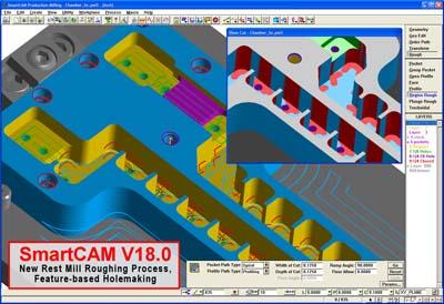
Version 18.0 is built on two central themes: core milling improvements, and core modeling and toolpath editing enhancements requested by customers. The new Rest-Mill Roughing capabilities, one of three a major core milling improvements in SmartCAM V18.0 milling applications, allow users to easily identify areas of remaining material, then machine those areas using a new Region Rough process. The Region Rough process machines the rest mill regions by automatically switching between profiling and pocketing strategies, depending on whether a region is open or closed. These new capabilities make it extremely fast and easy to re-machine features using progressively smaller tools.
In addition to the Rest Mill Roughing improvements, V18.0 introduces new Feature-based Hole-Making capabilities. Solid model hole-feature recognition has been enhanced to automatically identify compound hole-features, and create corresponding hole-feature elements which include full parametric detail of the hole. A new Hole Making process allows toolpath to be created by applying hole-making tools to a group of hole-feature elements, and automatically determining the start levels and hole depths from the input hole-features. The user has complete control over the hole-feature sequence, and the hole making processes can be modified and regenerated at ay time. These capabilities allow full automation for the creation of hole-making toolpath for common features, thereby saving time and ensuring accuracy and repeatability.
"Our last SmartCAM release focused on solids machining improvements in our advanced milling applications. For V18 we decided to concentrate on core milling functionality that will also benefit our SmartCAM Production Milling users," said Douglas Oliver, SmartCAMcnc's Senior Product Manager. "The wireframe rest-mill roughing and feature-based holemaking are fundamental capabilities that will be a huge time saver for all our milling users."
The third core milling improvement found in SmartCAM V18.0 is a set of enhancements related to the Helical Milling. Helix elements can now be created with left- or right-offset properties, and can be offset during verification and code generation. The Thread Milling process has been enhanced to take advantage of the new helix offsetting capabilities, as well as adding support for single point tools, tapered threads, multiple-side passes, and a user-specified lead extension. Additionally, changes to the code generator provide greater control over the output of straight and tapered spirals. These improvements are in direct response to frequent user requests for improved thread-milling support.
Additionally, a number of customer-requested core modeling and toolpath editing improvements can be found in all SmartCAM V18.0 applications, including machinable system fonts, a clip-to-intersection editing tool, improvements to toolpath verification and enhanced geometry layer mapping. Machinable Geometry from System Fonts now provides a full variety of font choices to the user. When a font is selected, SmartCAM extracts and scales the outline curves of the font and converts it to lines, polylines and arcs for use as machinable geometry.
The Clip-to-Intersection Editing Tool provides a method to split and remove geometry segments with a single click. This feature makes it remarkably easy to convert construction geometry into final part profiles. Two requested enhancements have been made to SmartCAM's Showpath Toolpath Verification functionality. A new Showpath option allows the verification to be restricted to only the portion of the model within the viewing window, and new configuration settings allow the tool motion speeds to be customized to better match the user's system capabilities and preferences. These two options allow a more efficient use of this heavily employed feature.
New Layer Mapping and Filtering Options allow better organization of the user's part geometry when importing CAD data into SmartCAM. SmartCAM layers can be pre-named and specific CAD layers can be directly mapped to SmartCAM layers. Additionally, specified layers not required for the manufacturing process can be filtered out of the import entirely. These features allows companies that use standardized CAD modeling layers to dramatically reduce the number of initial steps required to begin building toolpath for the model.
"We're very happy with the new core improvements based on SmartCAM customer requests," Douglas went on to say. "The new Clip to Intersection is a huge timesaver when editing wireframe geometry and toolpath. And the addition of machinable Windows Fonts is another frequently requested feature that will provide benefit to all SmartCAM users."
Contact Details
Related Glossary Terms
- computer-aided design ( CAD)
computer-aided design ( CAD)
Product-design functions performed with the help of computers and special software.
- computer-aided manufacturing ( CAM)
computer-aided manufacturing ( CAM)
Use of computers to control machining and manufacturing processes.
- electrical-discharge machining ( EDM)
electrical-discharge machining ( EDM)
Process that vaporizes conductive materials by controlled application of pulsed electrical current that flows between a workpiece and electrode (tool) in a dielectric fluid. Permits machining shapes to tight accuracies without the internal stresses conventional machining often generates. Useful in diemaking.
- gang cutting ( milling)
gang cutting ( milling)
Machining with several cutters mounted on a single arbor, generally for simultaneous cutting.
- milling
milling
Machining operation in which metal or other material is removed by applying power to a rotating cutter. In vertical milling, the cutting tool is mounted vertically on the spindle. In horizontal milling, the cutting tool is mounted horizontally, either directly on the spindle or on an arbor. Horizontal milling is further broken down into conventional milling, where the cutter rotates opposite the direction of feed, or “up” into the workpiece; and climb milling, where the cutter rotates in the direction of feed, or “down” into the workpiece. Milling operations include plane or surface milling, endmilling, facemilling, angle milling, form milling and profiling.
- milling machine ( mill)
milling machine ( mill)
Runs endmills and arbor-mounted milling cutters. Features include a head with a spindle that drives the cutters; a column, knee and table that provide motion in the three Cartesian axes; and a base that supports the components and houses the cutting-fluid pump and reservoir. The work is mounted on the table and fed into the rotating cutter or endmill to accomplish the milling steps; vertical milling machines also feed endmills into the work by means of a spindle-mounted quill. Models range from small manual machines to big bed-type and duplex mills. All take one of three basic forms: vertical, horizontal or convertible horizontal/vertical. Vertical machines may be knee-type (the table is mounted on a knee that can be elevated) or bed-type (the table is securely supported and only moves horizontally). In general, horizontal machines are bigger and more powerful, while vertical machines are lighter but more versatile and easier to set up and operate.
- profiling
profiling
Machining vertical edges of workpieces having irregular contours; normally performed with an endmill in a vertical spindle on a milling machine or with a profiler, following a pattern. See mill, milling machine.
- solid model
solid model
3-D model created using “building blocks.” This is the most accurate way of representing real-world objects in CAD.
- toolpath( cutter path)
toolpath( cutter path)
2-D or 3-D path generated by program code or a CAM system and followed by tool when machining a part.
- turning
turning
Workpiece is held in a chuck, mounted on a face plate or secured between centers and rotated while a cutting tool, normally a single-point tool, is fed into it along its periphery or across its end or face. Takes the form of straight turning (cutting along the periphery of the workpiece); taper turning (creating a taper); step turning (turning different-size diameters on the same work); chamfering (beveling an edge or shoulder); facing (cutting on an end); turning threads (usually external but can be internal); roughing (high-volume metal removal); and finishing (final light cuts). Performed on lathes, turning centers, chucking machines, automatic screw machines and similar machines.
- wire EDM
wire EDM
Process similar to ram electrical-discharge machining except a small-diameter copper or brass wire is used as a traveling electrode. Usually used in conjunction with a CNC and only works when a part is to be cut completely through. A common analogy is wire electrical-discharge machining is like an ultraprecise, electrical, contour-sawing operation.