The Umill 1800 from Mecof, part of EMCO Group, offers milling and turning solutions designed to meet the needs of mold makers, aerospace, automotive, and precision engineering users by offering precision, high dynamics, operational flexibility, and cost-effectiveness. Umill 1800 is a 5-axis milling center in a bridge design with moving table and crossbeam permitting loading from the top or the front of the machine.
Umill 1800 has a working range of 2,150 mm on the longitudinal axis Y, 1,800 mm on the cross X axis, and 1,250 mm in the vertical Z axis. Fourth and fifth axes are separately on the table and on the head, both with unique characteristics. The 5-axis machine can be equipped to work as a milling machine or as a multitasking solution for milling and turning operations. The table can be dedicated to milling (and therefore with a rotation speed of 10 rpm, transmission by means of torque motor, by 1.700x1.400 mm plate and a load capacity of 10 ton) or turning (up to 250 rpm, transmission by means of torque motor, plate with 1,800 mm diameter and a load capacity of 5 tons. Rapid traverse is 60 m/min. The movement of the table is carried out on two guideways size 65 with three trucks per guideway.
With these dimensions, the maximum workable piece has a diameter equal to 2500 mm. In case of turning operations, the spindle is locked by using a Hirth coupling/ face gears, thus disengaging the spindle and bearings from their stresses.
UMILL 1800 is equipped with two specific types of numerical controls, the Siemens 840D Solution Line or the Heidenhain TNC 640 HSCI able to manage both milling operations and turning operations. The head is available in two versions, which differ in the type of motor: a high-speed motor spindle (45 kW and 300 Nm in S1, HSK 100 and 12,000 rpm and beyond) and as an alternative, a 38 kW solution with mechanical transmission, tool taper ISO 50 or HSK 100, 600 Nm of torque in S1 and a rotation speed of up to 6,000 rpm.
The head has another unique feature connected to the rotary axis: its shape allows positioning the tool for working in undercut up to -15 °. In the horizontal position the tool axis is exactly aligned with the direction of the table movement. Other machines cannot orient it in the same way; and then to perform an operation along the Y-axis they must interpolate the axes X and Y. Being able to engage a single axis, however, has accuracy advantages, thrust force benefits, and a reduction of complexity in programming.
The structure of the Umill 1800 is composed of three main parts rigidly attached to each other; so installation time is minimized. The machine can be located on the workshop floor without having to build expensive foundation and without interfering with current production.
The machine configuration supports optimum machining dynamics at any point within the working volume: the head overhang is the same regardless of the position of the axes. Without components such as rams that modify the geometric conditions, it ensures maximum repeatability and precision. The volumetric accuracy, calculated on the basis of an ideal diagonal within the working range, is among the most accurate available anywhere.
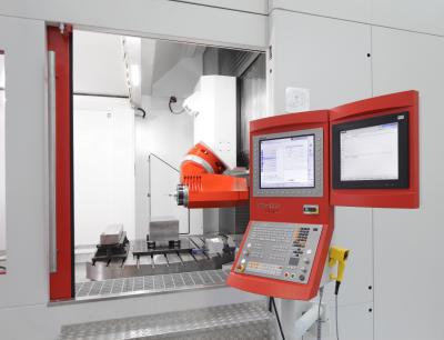
In addition to the numerical control panel positioned at the side of the machine, at the back there is an additional panel dedicated to the tool magazine management (from 64 up to 228 pockets), which can also be managed in while in process to perform the tool refresh, addition or replacement.
The control system communicates with drives, measuring systems and motors via digital signals. In addition to increased speed in transmission and information management, the main advantage is the elimination of the signal noise.
IES (Integrated Energy Saving) is a system integrated in the numerical control that, through the latest generation of drives, permits energy recovery during braking and releasing it back into the grid. You can also set the process to ‘stand-by’, ‘automatic’ or ‘off’, configurable by the operator.
There has also been an emphasis on machine maintainability, which is facilitated by the experience gained by Mecof with several important manufacturers in the automotive sector that required an approach linked to the philosophy WCM (World Class Manufacturing).
Standard package Safety Integrated incorporates all the functions related to security management (electrical locks, clamping, spindle rotation in case of emergency, etc.), which are wholly managed by the CNC.
In terms of options, Mecof has created some packages that can further enhance the capabilities and the operational reliability of the machine. In case of a power failure, for example, the ESR function (Extended System Retraction) releases the tool axis in positive direction: without this device, the operating time of the machine brakes would not be enough to avoid an axis "failure" which, although in the order of hundredths of a millimeter, would leave a mark on the piece or, at worst, would result in a tool breakage or on a part damage.
With the OMHK option the operator has the possibility to calibrate the milling head and the rotary table, optimizing the kinematics of the machine for 5-axis operation. The graphics interface has been customized to be easier to understand and manage: in maintenance, for example, control and check pages include recall alert in case of preventive or scheduled service interventions, deadlines, fill-ups, etc.
Also, screen pages display wear monitoring data of key components such as screws, guideways, pads, spindles, bearings, etc.
Full guarding contains the cooling lubricants: the coolant and the chips are then conveyed by two lateral screw conveyors to a filtering device that handles separately the chips (recovered in classic container) and the liquid (filtered and recirculated back into the tank). The main door, with electromechanical interlock, allows front and top access for easy manual loading or by overhead crane.
Monitoring of tool conditions can be assigned to a series of integrated sensors (one sensitive to vibrations and one to forces) that allows to determine the optimum working conditions, and to set a threshold for intervention beyond which it is necessary to proceed with the reduction of working parameters or stop the machine.
Contact Details
Related Glossary Terms
- computer numerical control ( CNC)
computer numerical control ( CNC)
Microprocessor-based controller dedicated to a machine tool that permits the creation or modification of parts. Programmed numerical control activates the machine’s servos and spindle drives and controls the various machining operations. See DNC, direct numerical control; NC, numerical control.
- coolant
coolant
Fluid that reduces temperature buildup at the tool/workpiece interface during machining. Normally takes the form of a liquid such as soluble or chemical mixtures (semisynthetic, synthetic) but can be pressurized air or other gas. Because of water’s ability to absorb great quantities of heat, it is widely used as a coolant and vehicle for various cutting compounds, with the water-to-compound ratio varying with the machining task. See cutting fluid; semisynthetic cutting fluid; soluble-oil cutting fluid; synthetic cutting fluid.
- gang cutting ( milling)
gang cutting ( milling)
Machining with several cutters mounted on a single arbor, generally for simultaneous cutting.
- milling
milling
Machining operation in which metal or other material is removed by applying power to a rotating cutter. In vertical milling, the cutting tool is mounted vertically on the spindle. In horizontal milling, the cutting tool is mounted horizontally, either directly on the spindle or on an arbor. Horizontal milling is further broken down into conventional milling, where the cutter rotates opposite the direction of feed, or “up” into the workpiece; and climb milling, where the cutter rotates in the direction of feed, or “down” into the workpiece. Milling operations include plane or surface milling, endmilling, facemilling, angle milling, form milling and profiling.
- milling machine ( mill)
milling machine ( mill)
Runs endmills and arbor-mounted milling cutters. Features include a head with a spindle that drives the cutters; a column, knee and table that provide motion in the three Cartesian axes; and a base that supports the components and houses the cutting-fluid pump and reservoir. The work is mounted on the table and fed into the rotating cutter or endmill to accomplish the milling steps; vertical milling machines also feed endmills into the work by means of a spindle-mounted quill. Models range from small manual machines to big bed-type and duplex mills. All take one of three basic forms: vertical, horizontal or convertible horizontal/vertical. Vertical machines may be knee-type (the table is mounted on a knee that can be elevated) or bed-type (the table is securely supported and only moves horizontally). In general, horizontal machines are bigger and more powerful, while vertical machines are lighter but more versatile and easier to set up and operate.
- numerical control ( NC)
numerical control ( NC)
Any controlled equipment that allows an operator to program its movement by entering a series of coded numbers and symbols. See CNC, computer numerical control; DNC, direct numerical control.
- rapid traverse
rapid traverse
Movement on a CNC mill or lathe that is from point to point at full speed but, usually, without linear interpolation.
- recovery
recovery
Reduction or removal of workhardening effects, without motion of large-angle grain boundaries.
- turning
turning
Workpiece is held in a chuck, mounted on a face plate or secured between centers and rotated while a cutting tool, normally a single-point tool, is fed into it along its periphery or across its end or face. Takes the form of straight turning (cutting along the periphery of the workpiece); taper turning (creating a taper); step turning (turning different-size diameters on the same work); chamfering (beveling an edge or shoulder); facing (cutting on an end); turning threads (usually external but can be internal); roughing (high-volume metal removal); and finishing (final light cuts). Performed on lathes, turning centers, chucking machines, automatic screw machines and similar machines.
- undercut
undercut
In numerical-control applications, a cut shorter than the programmed cut resulting after a command change in direction. Also a condition in generated gear teeth when any part of the fillet curve lies inside of a line drawn tangent to the working profile at its point of juncture with the fillet. Undercut may be deliberately introduced to facilitate finishing operations, as in preshaving.