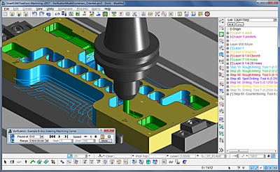
SmartCAMcnc has announced the release of SmartCAM v2017. SmartCAM v2017 delivers new verification technology, as well as expanded rotary axis and code generation support, and improvements to the user interface and rough milling functionality. The SmartCAM CAM software family consists of toolpath creation applications for CNC milling, turning, fabrication and wire EDM.
SmartCAM v2017 introduces a new integrated Verify module that replaces the separate ShowPath and ShowCut toolpath and material-removal verification functions of previous products. All verification is now performed in the main SmartCAM graphics window. Dynamic viewing and standard system display functionality is fully supported. Toolpath animation and back-plotting can be simultaneously viewed during material removal simulation.
The new SmartCAM verification uses the proven ModuleWorks simulation technology, and offers improved model accuracy and collision checking capabilities.
"Over the years we've had many customer requests to improve our material removal verification, in particular the ability to change the view while simulating. The new Verify module with its full dynamic viewing and tremendously improved capabilities, really delivers on those requests." said Doug Oliver, senior product manager at SmartCAMcnc.
"The new compact and simplified user interface provides much improved control. Users can now step through verification while automatically pausing after each move, element, or step." Douglas added. "Additionally, it's now possible to store the in-process stock model at any point during verification so it can be exported in standard STL format, or used as input to subsequent verification."
SmartCAM milling users will benefit from an updated Open Profile process, which uses new regioning technology to handle a wider set of geometric situations, and now includes lead in/out and cutter comp support, allowing it to be used for semifinishing and finishing applications. Rotary axis support has been enhanced and now includes features for specifying angle limits, and Euler angles for tilted plane commands, to name a few.
Numerous core improvements like drag and drop of the insert position or elements and nodes in the hierarchical list view, and enhanced code generation with new debugging and error checking capabilities, benefit all SmartCAM users. Additionally, SmartCAM v2017 incorporates the latest ACIS 2017 kernel with updated CAD data translators for SolidWorks and Inventor 2017, and Solid Edge ST9.
"SmartCAM v2017 marks the start of what we hope will be a long, productive relationship with ModuleWorks. We are excited by all the technology available to us, and think our customers will be as well when they receive more frequent and significant improvements to their SmartCAM products," said Oliver.
Contact Details
Related Glossary Terms
- computer numerical control ( CNC)
computer numerical control ( CNC)
Microprocessor-based controller dedicated to a machine tool that permits the creation or modification of parts. Programmed numerical control activates the machine’s servos and spindle drives and controls the various machining operations. See DNC, direct numerical control; NC, numerical control.
- computer-aided design ( CAD)
computer-aided design ( CAD)
Product-design functions performed with the help of computers and special software.
- computer-aided manufacturing ( CAM)
computer-aided manufacturing ( CAM)
Use of computers to control machining and manufacturing processes.
- electrical-discharge machining ( EDM)
electrical-discharge machining ( EDM)
Process that vaporizes conductive materials by controlled application of pulsed electrical current that flows between a workpiece and electrode (tool) in a dielectric fluid. Permits machining shapes to tight accuracies without the internal stresses conventional machining often generates. Useful in diemaking.
- gang cutting ( milling)
gang cutting ( milling)
Machining with several cutters mounted on a single arbor, generally for simultaneous cutting.
- milling
milling
Machining operation in which metal or other material is removed by applying power to a rotating cutter. In vertical milling, the cutting tool is mounted vertically on the spindle. In horizontal milling, the cutting tool is mounted horizontally, either directly on the spindle or on an arbor. Horizontal milling is further broken down into conventional milling, where the cutter rotates opposite the direction of feed, or “up” into the workpiece; and climb milling, where the cutter rotates in the direction of feed, or “down” into the workpiece. Milling operations include plane or surface milling, endmilling, facemilling, angle milling, form milling and profiling.
- toolpath( cutter path)
toolpath( cutter path)
2-D or 3-D path generated by program code or a CAM system and followed by tool when machining a part.
- turning
turning
Workpiece is held in a chuck, mounted on a face plate or secured between centers and rotated while a cutting tool, normally a single-point tool, is fed into it along its periphery or across its end or face. Takes the form of straight turning (cutting along the periphery of the workpiece); taper turning (creating a taper); step turning (turning different-size diameters on the same work); chamfering (beveling an edge or shoulder); facing (cutting on an end); turning threads (usually external but can be internal); roughing (high-volume metal removal); and finishing (final light cuts). Performed on lathes, turning centers, chucking machines, automatic screw machines and similar machines.
- wire EDM
wire EDM
Process similar to ram electrical-discharge machining except a small-diameter copper or brass wire is used as a traveling electrode. Usually used in conjunction with a CNC and only works when a part is to be cut completely through. A common analogy is wire electrical-discharge machining is like an ultraprecise, electrical, contour-sawing operation.
