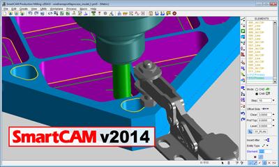
SmartCAMcnc has announced the release of SmartCAM v2014. SmartCAM v2014 delivers a redesigned and improved user interface that assists in usability, ease of learning and user efficiency, plus a variety of milling process modeling, toolpath verification and geometry modeling improvements.
The SmartCAM product family consists of Computer-Aided Manufacturing (CAM) applications for CNC milling, turning, fabrication and wire EDM.
SmartCAM v2014 introduces extensive user interface updates that give the product a more modern look and feel while also making it easier to learn and use. New panel task menus and customizable toolbars make it more convenient to access frequently used commands, and new configuration options allow the system to be tailored to make best use of screen workspace.
Additionally, the SmartCAM Undo mechanism has been completely rewritten to allow multiple Undo or Redo of all modeling tasks, a significant advantage over previous versions.
"SmartCAM v2014 users will first notice the new user interface which is a logical evolution of the familiar SmartCAM modeling environment," said Douglas Oliver, SmartCAMcnc's Senior Product Manager. "The new task bar menus, coupled with the ability to configure custom toolbars provide users extremely quick and convenient access to their most-commonly used tasks, substantially improving efficiency and productivity. And of course the new Undo allows users the flexibility to try various machining strategies with the ability to quickly revert to a prior model state. That is a huge improvement that every user will enjoy."
Improvements to the milling processes increase toolpath reliability and efficiency, and reduce the number of steps required to remachine remaining material and generate wireframe profiling toolpath. New arc connections in SmartCAM's Facing and Region Rough processes provide a "high-speed machining" technique that prevents abrupt direction changes which may be potentially harmful to machinery.
The ShowCut and ShowPath toolpath verification modules have been enhanced to make better use of standard tooling by providing improved visualization of turning-tool holders, and allowing milling-tool holders to be used with parametrically defined tools. New collision reporting and holder checking capabilities assists users in finding potential problems.
SmartCAM v2014 also boasts a number of significant improvements to SmartCAM's modeling capabilities. These improvements make it easier to define complex profiles using limited dimensional data, or by performing Boolean modeling operations on multiple closed boundaries.
All SmartCAM v2014 products will benefit from an updated ACIS modeling kernel as well as updated native and generic data translators.
Contact Details
Related Glossary Terms
- computer numerical control ( CNC)
computer numerical control ( CNC)
Microprocessor-based controller dedicated to a machine tool that permits the creation or modification of parts. Programmed numerical control activates the machine’s servos and spindle drives and controls the various machining operations. See DNC, direct numerical control; NC, numerical control.
- computer-aided manufacturing ( CAM)
computer-aided manufacturing ( CAM)
Use of computers to control machining and manufacturing processes.
- electrical-discharge machining ( EDM)
electrical-discharge machining ( EDM)
Process that vaporizes conductive materials by controlled application of pulsed electrical current that flows between a workpiece and electrode (tool) in a dielectric fluid. Permits machining shapes to tight accuracies without the internal stresses conventional machining often generates. Useful in diemaking.
- gang cutting ( milling)
gang cutting ( milling)
Machining with several cutters mounted on a single arbor, generally for simultaneous cutting.
- milling
milling
Machining operation in which metal or other material is removed by applying power to a rotating cutter. In vertical milling, the cutting tool is mounted vertically on the spindle. In horizontal milling, the cutting tool is mounted horizontally, either directly on the spindle or on an arbor. Horizontal milling is further broken down into conventional milling, where the cutter rotates opposite the direction of feed, or “up” into the workpiece; and climb milling, where the cutter rotates in the direction of feed, or “down” into the workpiece. Milling operations include plane or surface milling, endmilling, facemilling, angle milling, form milling and profiling.
- profiling
profiling
Machining vertical edges of workpieces having irregular contours; normally performed with an endmill in a vertical spindle on a milling machine or with a profiler, following a pattern. See mill, milling machine.
- toolpath( cutter path)
toolpath( cutter path)
2-D or 3-D path generated by program code or a CAM system and followed by tool when machining a part.
- turning
turning
Workpiece is held in a chuck, mounted on a face plate or secured between centers and rotated while a cutting tool, normally a single-point tool, is fed into it along its periphery or across its end or face. Takes the form of straight turning (cutting along the periphery of the workpiece); taper turning (creating a taper); step turning (turning different-size diameters on the same work); chamfering (beveling an edge or shoulder); facing (cutting on an end); turning threads (usually external but can be internal); roughing (high-volume metal removal); and finishing (final light cuts). Performed on lathes, turning centers, chucking machines, automatic screw machines and similar machines.
- wire EDM
wire EDM
Process similar to ram electrical-discharge machining except a small-diameter copper or brass wire is used as a traveling electrode. Usually used in conjunction with a CNC and only works when a part is to be cut completely through. A common analogy is wire electrical-discharge machining is like an ultraprecise, electrical, contour-sawing operation.