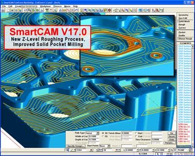
SmartCAMcnc has announced the field test release of SmartCAM V17.0. Version 17.0 delivers advanced milling improvements including a new Z-level roughing process and enhancements to the solid pocketing process, and substantial core enhancements to the entire SmartCAM suite of CAM system software, including Web-format report generation, improvements to graphics printing and new capabilities to store the mask and visibility state with named views. Version 17.0 continues the solids-machining theme found in the many recent releases, and provides significant benefits for milling users working with both prismatic and freeform solid models. The new Z-Level Rough process incorporates the many features found in the Solid Pocket process introduced in v16, such as critical depth processing and multiple start points, and extends these capabilities to allow roughing strategies to be applied to virtually any part configuration consisting of cores, cavity, and open pockets and profiles. The new process is found in SmartCAM Advanced Milling, Advanced Turning and FreeForm Machining applications. The roughing regions are determined based on the selected part features and a specified stock. Roughing strategies can be automatically switched, for example, applying inside out spiral strategies to cavity regions, and outside in to cores. Additionally, open profile regions can be machined with unidirectional or bidirectional profiling passes. These new capabilities save time and reduce job complexity by allowing one machining process to efficiently machine many varying features. A new HTML-based report generator added to all SmartCAM applications greatly improves the flexibility and quality of job and shop floor documentation, according to the company. The new Web report generator allows a single report to include both tool and process step information along with job header and part graphic images. The customizable report format framework provides users to ability to tailor their reports to fit their exact needs, for example, adding tool and model images or other pertinent detail. Enhancements to graphic printing provide high-resolution printouts that can be scaled directly to the current system units. A new print preview allows print settings to be verified before generating the printout. The existing Named View capabilities have been extended to allow users to specify exactly which view parameters are to be captured with the named view. View orientation, size and position, mask and visibility states can all be specified and saved independently. These capabilities allow users to toggle between various views that would have required the execution of many commands to replicate in previous versions. Additionally predefined named views can now be referenced when generating job reports, allowing corresponding images to be captured and embedded in the report automatically.
Contact Details
Related Glossary Terms
- computer-aided manufacturing ( CAM)
computer-aided manufacturing ( CAM)
Use of computers to control machining and manufacturing processes.
- gang cutting ( milling)
gang cutting ( milling)
Machining with several cutters mounted on a single arbor, generally for simultaneous cutting.
- milling
milling
Machining operation in which metal or other material is removed by applying power to a rotating cutter. In vertical milling, the cutting tool is mounted vertically on the spindle. In horizontal milling, the cutting tool is mounted horizontally, either directly on the spindle or on an arbor. Horizontal milling is further broken down into conventional milling, where the cutter rotates opposite the direction of feed, or “up” into the workpiece; and climb milling, where the cutter rotates in the direction of feed, or “down” into the workpiece. Milling operations include plane or surface milling, endmilling, facemilling, angle milling, form milling and profiling.
- profiling
profiling
Machining vertical edges of workpieces having irregular contours; normally performed with an endmill in a vertical spindle on a milling machine or with a profiler, following a pattern. See mill, milling machine.
- turning
turning
Workpiece is held in a chuck, mounted on a face plate or secured between centers and rotated while a cutting tool, normally a single-point tool, is fed into it along its periphery or across its end or face. Takes the form of straight turning (cutting along the periphery of the workpiece); taper turning (creating a taper); step turning (turning different-size diameters on the same work); chamfering (beveling an edge or shoulder); facing (cutting on an end); turning threads (usually external but can be internal); roughing (high-volume metal removal); and finishing (final light cuts). Performed on lathes, turning centers, chucking machines, automatic screw machines and similar machines.
- web
web
On a rotating tool, the portion of the tool body that joins the lands. Web is thicker at the shank end, relative to the point end, providing maximum torsional strength.