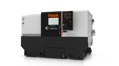
Mazak’s QTU-200MY multitask turning center reportedly offers shops of all sizes ease of use, cost-effectiveness and unmatched productivity. The space-saving machine features a main turning spindle, tool turret with rotary milling spindle, Mazak’s new MAZATROL SmoothC control and Y-axis off-centerline capabilities for high versatility paired with all the benefits of multitasking part processing.
The machine’s headstock incorporates Mazak’s (built-in) spindle/motor design that eliminates the need for belts or pulleys for zero backlash or any belt stick/slip. The A2-6, 20-hp (15 kW)(15% ED) main turning spindle provides speeds from 35 rpm up to 6,000 rpm with 90 ft.-lbs. of torque for heavy-duty metal removal. Its spindle bore diameter of 2.4” (61 mm) accommodates a maximum bar diameter of 2” (42 mm).
The main turning spindle also serves as a full 360-degree C-axis that indexes in 0.001-degree increments. It is a full-function CNC programmable axis that accurately positions parts for complex and prismatic machining along with 3D contouring.
Additionally, the QTU-200MY is outfitted with a 12-position, integral-motor turret that uses a roller gear cam drive system for smooth, high-speed, high-accuracy digital indexing as well as expandability. The innovative turret eliminates the need for curvic/index couplings and with the use of tandem tooling, allows the number of tool positions to be expanded. This is possible because it indexes digitally to any position without changes to the turret housing. And once in position, an integral hydraulic clamping system ensures maximum rigidity.
The turret’s rotary tool spindle delivers 4,500 rpm (standard) and 6,000 rpm (optional) to perform milling, drilling and tapping operations. The standard mill spindle provides 34.7 ft.-lbs. of torque, while the optional higher speed version generates 17 ft.-lbs.
Because it features Y-axis off-centerline machining capability, the QTU-200MY uses Mazak’s special high-gain servo-control turret/feed-axis motion. The double-slide configuration delivers rigid, high-speed, precise positioning as well as smooth axis acceleration/deceleration. The machine’s X-axis ballscrews work in tandem with the Y-axis ballscrews that are inclined at 30 degrees to move the turret 3.94” (100 mm) in the Y axis.
The machine also features an NC servo-driven tailstock to enable automated processes. The fully programmable tailstock utilizes its own AC servomotor and ball screw. Through the part program, the tailstock extends to a known position and with an approach feed rate, makes contact with the part with consistent holding pressure. Because of its positive independent drive system, the tailstock can drill holes on shaft centerlines, which adds versatility to the jobs it can process.
Tailstock thrust settings are adjustable in increments of 22.5 ft.-lbs. of force. This provides users the option to set thrust levels according to workpiece material and shape. A capability that eliminates the risk of part damage while simultaneously providing safe and secure holding and support with thrust settings between 225 lbs. (minimum) and 1,1124 lbs. (maximum).
The QTU-200MY MAZATROL SmoothC CNC offers EIA/ISO programming as well as conversational programming that makes it easy to generate programs for angled drilling, milling or tapping operations. The control also features advanced hardware and software functions that help ensure high productivity and performance accuracy in complex part production.
With a new high-rigidity base/bed design, the QTU-200MY ensures thermal control, ample part capacity and speed stability. The machine’s swing capacity measures 27.4” (696 mm), and it accommodates part diameters up to 13.4” (340 mm). Rapid traverse rates are 1,181 ipm (30 m/min) in the X axis and 1,417 imp (36 m/min) in Z.
A variety of automation strategies can be integrated with the QTU-200MY, from an automatic bar feeder to gantry robots and custom solutions, for improved spindle utilization and a significant boost in productivity, according to the company.
Contact Details
Related Glossary Terms
- backlash
backlash
Reaction in dynamic motion systems where potential energy that was created while the object was in motion is released when the object stops. Release of this potential energy or inertia causes the device to quickly snap backward relative to the last direction of motion. Backlash can cause a system’s final resting position to be different from what was intended and from where the control system intended to stop the device.
- computer numerical control ( CNC)
computer numerical control ( CNC)
Microprocessor-based controller dedicated to a machine tool that permits the creation or modification of parts. Programmed numerical control activates the machine’s servos and spindle drives and controls the various machining operations. See DNC, direct numerical control; NC, numerical control.
- computer-aided manufacturing ( CAM)
computer-aided manufacturing ( CAM)
Use of computers to control machining and manufacturing processes.
- conversational programming
conversational programming
Method for using plain English to produce G-code file without knowing G-code in order to program CNC machines.
- feed
feed
Rate of change of position of the tool as a whole, relative to the workpiece while cutting.
- gang cutting ( milling)
gang cutting ( milling)
Machining with several cutters mounted on a single arbor, generally for simultaneous cutting.
- inches per minute ( ipm)
inches per minute ( ipm)
Value that refers to how far the workpiece or cutter advances linearly in 1 minute, defined as: ipm = ipt 5 number of effective teeth 5 rpm. Also known as the table feed or machine feed.
- milling
milling
Machining operation in which metal or other material is removed by applying power to a rotating cutter. In vertical milling, the cutting tool is mounted vertically on the spindle. In horizontal milling, the cutting tool is mounted horizontally, either directly on the spindle or on an arbor. Horizontal milling is further broken down into conventional milling, where the cutter rotates opposite the direction of feed, or “up” into the workpiece; and climb milling, where the cutter rotates in the direction of feed, or “down” into the workpiece. Milling operations include plane or surface milling, endmilling, facemilling, angle milling, form milling and profiling.
- milling machine ( mill)
milling machine ( mill)
Runs endmills and arbor-mounted milling cutters. Features include a head with a spindle that drives the cutters; a column, knee and table that provide motion in the three Cartesian axes; and a base that supports the components and houses the cutting-fluid pump and reservoir. The work is mounted on the table and fed into the rotating cutter or endmill to accomplish the milling steps; vertical milling machines also feed endmills into the work by means of a spindle-mounted quill. Models range from small manual machines to big bed-type and duplex mills. All take one of three basic forms: vertical, horizontal or convertible horizontal/vertical. Vertical machines may be knee-type (the table is mounted on a knee that can be elevated) or bed-type (the table is securely supported and only moves horizontally). In general, horizontal machines are bigger and more powerful, while vertical machines are lighter but more versatile and easier to set up and operate.
- numerical control ( NC)
numerical control ( NC)
Any controlled equipment that allows an operator to program its movement by entering a series of coded numbers and symbols. See CNC, computer numerical control; DNC, direct numerical control.
- rapid traverse
rapid traverse
Movement on a CNC mill or lathe that is from point to point at full speed but, usually, without linear interpolation.
- tapping
tapping
Machining operation in which a tap, with teeth on its periphery, cuts internal threads in a predrilled hole having a smaller diameter than the tap diameter. Threads are formed by a combined rotary and axial-relative motion between tap and workpiece. See tap.
- turning
turning
Workpiece is held in a chuck, mounted on a face plate or secured between centers and rotated while a cutting tool, normally a single-point tool, is fed into it along its periphery or across its end or face. Takes the form of straight turning (cutting along the periphery of the workpiece); taper turning (creating a taper); step turning (turning different-size diameters on the same work); chamfering (beveling an edge or shoulder); facing (cutting on an end); turning threads (usually external but can be internal); roughing (high-volume metal removal); and finishing (final light cuts). Performed on lathes, turning centers, chucking machines, automatic screw machines and similar machines.

