NUMROTO Grinding Software
NUMROTO Grinding Software
Tool manufacturers can now automatically create dimensioned engineering drawings of machine tools showing their precise geometry, by using a new facility for NUM's renowned NUMROTO grinding software.

Tool manufacturers can now automatically create dimensioned engineering drawings of machine tools showing their precise geometry, by using a new facility for NUM's renowned NUMROTO grinding software. By producing cross-sectional views of a tool at any position along its length the new NUMROTO Draw function can effectively automate production verification. The drawings can also incorporate images obtained directly from 3D simulation of a tool, enabling even complex grinding details to be portrayed graphically and unequivocally.
NUMROTO Draw is ideal for tool manufacturers seeking a means of showing customers precise details of tools prior to production, or of confirming the ground geometry of a tool as part of the delivery process. The software is also likely to prove popular with tool resharpening companies, as it enables them to provide customers with documented confirmation of work, either before or after it has been carried out.
Most product documentation software packages for multi-axis tool grinding that are currently on the market take the form of relatively simple drawing generators. They are generally limited to a single type of tool, such as a drill, and present information as parameterized drawings. Whilst these are adequate for documenting the outer geometry of a tool, they are not suitable for showing the precise cross-sectional details of a complex ground geometry.
NUMROTO Draw overcomes these limitations through tight integration with the core NUMROTO software, which provides a wealth of data sources. The drawing is derived directly from the same data source as the CNC program, ensuring there is no ambiguity in the process. Using data that defines the spatial course of the tool's cutting edge, the software automatically calculates all dimensions that require presentation and then generates the appropriate drawing. If any of the dimensions do not meet a customer's requirement, they can be amended very easily.
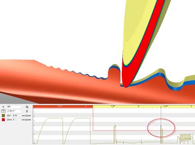
Provided that the NUMROTO program also includes the grinding wheel data, NUMROTO Draw can process this information to create 3D details and integrate them with the drawing. The 3D details can be represented as color images or as wire frame models, and provide an extremely accurate portrayal of the tool's profile or cross sectional geometry between or at any position(s) along its length.
The drawings created by NUMROTO Draw are fully editable. Header information can be structured by the user to suit the customer's requirements, and the tool designation can be taken directly from the NUMROTO database. A separate table, showing the main parameters of the tool, can either be created by the user or adapted from one of the templates supplied by NUM, and again can be populated using values from the NUMROTO database to help save time. The documentation – which can be structured to occupy several pages if desired can also include a graphical representation of the grinding wheel pack, together with a table containing information about each wheel, such as its diameter, width and grinding angle.
According to Patrick Schmid, head of research and development for NUM's NUMROTO group, "Our software is extremely popular with tool manufacturers and resharpening companies there are over 3,000 installations of NUMROTO, spread across more than 50 different types of machine. NUMROTO Draw is the latest technological milestone in the evolution of tool grinding software. By effectively automating product documentation, it will help users accelerate production verification, aid quality control, and lead to faster order delivery."
NUM believes that its new NUMROTO Draw facility also helps to shorten the sampling process. Customers of tool grinding companies often describe their requirement for a new tool vocally, with the help of hand-drawn sketches. After creating the CNC program for the tool grinding machine, the company then grinds a sample tool it is only at this stage that any necessary revisions to the design become apparent, and the process is often highly iterative. Using NUMROTO Draw, companies can now present customers with a drawing showing the precise grindable geometry of the tool very early in the development cycle. A 3D model can also be created, enabling the customer to view the proposed tool from various perspectives. Any design changes can then be implemented immediately, prior to grinding a sample tool, speeding the process while minimizing costs and scrap.
Coincident with the launch of NUMROTO Draw, NUM has also further enhanced the capabilities of NUMROTO in a number of key areas. The number and type of measurements that can be performed during grinding operations has been extended significantly. Typically, operators can now maintain tolerances to within +/-3µm, even when producing a wide range of tools that may involve as many as 15 different measurements. The software also now features an XML data interface, enabling tool geometry parameters such as length, diameter, rake angle, relief information and many others to be exported for use in other programs, or imported from a customer's database to shorten the design-to-production path.


