An array of new and enhanced functionality keeps the latest digital twin software from Hexagon Production Software at the very forefront of Industry 4.0 Smart Factory technology by increasing CNC program quality with automatic and predictive analysis.
NCSIMUL virtually builds the real-life machining environment to avoid errors, decrease set-up times and switch CNC programs between machines.
The 2021 release features a new comparison mode that detects excessive material during a fast and hidden simulation. It shows a solid comparison between the CAD/CAM models or previous cut stock and the NCSIMUL simulated model.
Technical Director Philippw Legoupi ays this new item of functionality is the only way to detect unwanted rest stock on a large part. It shows a list of the excess material that’s left, and can also be displayed in a 3D window linked to the list. Among its numerous benefits are the abilities to find small, missing drill holes on large aerospace components and missing holes that need to be connected on mold bodies and hydraulic parts.
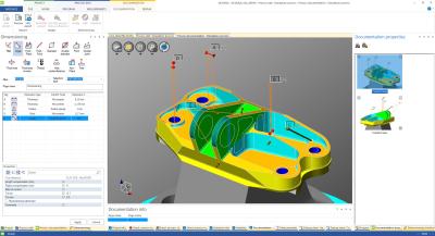
Integrated to NCDoc, Dimensioning is a new function which creates control instructions for operators during the CNC process. It defines a dimension check-list with user-defined tolerances, automatically defines the minimum measurement needed for each cut, generates a comprehensive view for the programmer and operator on the 3D simulation, and works with the NCDoc documentation template. This saves time and money, particularly when using the Wizard to create the correct number of measurements, even when using a probe tool on the machine.
A new set of options quickly evaluate tools that can benefit from air-cutting optimization, with the ‘out of material working time’ in the sequence list. This works with the NCDoc documentation template, and customizes stock nearness values for each sequence; the optimization is automatically stored for future strategies.
Enhancements to editing Setup reduce simulation time by merging fixtures, parts and rough stock elements from one, or multiple, CAD files read in NCSIMUL. “It creates simple, geometric rough stock – either cylinder or cubes – an automatic part envelope, and all setup elements can move up or down,” Legoupi says.
Improvements to mill-turn tooling include management for ESPRIT CAM and TopSolid CAM interfaces: With a new ‘Configuration interface file’ associated to each digital twin, it is now possible to define the mapping of tool-assembly positioning – station number, turret and orientation – between the CAM system and NCSIMUL. This means the interfaces can create NCSIMUL projects ready to run the simulation.
A simplified 2D display for turning parts improves the analysis of dynamic rough stock. Legoupi explains, “It quickly displays the tool and toolpath next to the cut model and reference part profiles.”
The document center is now available online, and includes additional descriptions of the released versions, including more details under the ‘case studies’ and ‘focus on’ tabs.
Finally, for cutting-tool wear simulation as defined in the tool magazine, a button now runs the simulation for tools either ‘fresh out of the box,’ or ‘worn down.’ User-defined values apply for each cutting tool, and the system can check if a worn tool will generate alarms or collisions with unwanted rest stock material. This defines the sharpening rules, and decreases tool consumption.
Concluding, Legoupi says, “The enhanced functionality in NCSIMUL 2021 further increases shop-floor productivity and reduces manufacturing costs.”
Contact Details
Related Glossary Terms
- computer numerical control ( CNC)
computer numerical control ( CNC)
Microprocessor-based controller dedicated to a machine tool that permits the creation or modification of parts. Programmed numerical control activates the machine’s servos and spindle drives and controls the various machining operations. See DNC, direct numerical control; NC, numerical control.
- computer-aided design ( CAD)
computer-aided design ( CAD)
Product-design functions performed with the help of computers and special software.
- computer-aided manufacturing ( CAM)
computer-aided manufacturing ( CAM)
Use of computers to control machining and manufacturing processes.
- toolpath( cutter path)
toolpath( cutter path)
2-D or 3-D path generated by program code or a CAM system and followed by tool when machining a part.
- turning
turning
Workpiece is held in a chuck, mounted on a face plate or secured between centers and rotated while a cutting tool, normally a single-point tool, is fed into it along its periphery or across its end or face. Takes the form of straight turning (cutting along the periphery of the workpiece); taper turning (creating a taper); step turning (turning different-size diameters on the same work); chamfering (beveling an edge or shoulder); facing (cutting on an end); turning threads (usually external but can be internal); roughing (high-volume metal removal); and finishing (final light cuts). Performed on lathes, turning centers, chucking machines, automatic screw machines and similar machines.


