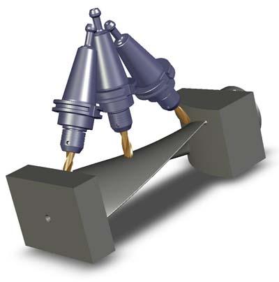
Multiaxis machining from CNC Software Inc. can dramatically increase a shop's competitiveness. Mastercam's multiaxis machining offers a wide range of multiaxis machining strategies, both basic and advanced. With Mastercam, you have complete control over the three crucial elements of multiaxis machining: Cut Pattern, Tool Axis Control, and Collision Control. Mastercam X5 introduces a unified interface and a streamlined workflow for generating multiaxis toolpaths.
Cut Patterns guide the tool along specified paths. These patterns can be simple 2D and 3D wireframe, solid primitives (for example, box, cylinder, or sphere), or complex multisurface grids. Mastercam's Multiaxis machining has many toolpath types to govern the cut pattern including: Curve wireframe for trimming operations, Swarf fanning and swarf machining over multisurface floors, plus rail swarf cutting for added control, Multisurface 5-axis roughing and finishing, including depth cuts, plunge roughing, and flowline machining and drilling, Stock recognition that trims toolpaths to eliminate air-cuts and drastically reduce cycle times, Custom applications for machining cylinder heads and converting probe data to machinable geometry, and Mastercam X5 introduces eight new triangular mesh multiaxis toolpaths that support surface, solid, and STL input.
Mastercam's Tool Axis Control allows orientation of the tool's center axis to be manipulated as it follows the cut pattern. You have complete and dynamic control over the tool axis, lead/lag, entry/exit, and tilt, which simplifies even the most difficult multiaxis jobs. Full entry and exit control lets you determine exactly where and how the cutter enters and leaves your part. An automatic point generator adds greater precision, as well as advanced gouge checking and a 5-axis safe zone around the part. Powerful axis limits control tool motion between defined angles, ensuring that the tool tilt does not violate part or machine tool limits. You can easily refine control of your tool axis with a few simple pieces of CAD geometry. Shank containment simplifies cutting in confined areas.
When programming 5-axis parts, it is often necessary to come very close to the part or fixture with either the cutter, arbor, or the holder. Mastercam gives you "near miss tolerance" fields so you can specify how close you are willing to get with any part of the tool and how to avoid those situations.
Mastercam X5 introduces a unified interface and a streamlined workflow for multiaxis toolpaths. The selection screen tree structure changes based on toolpath family and type selections. The tree is laid out in the logical order of setting your toolpath parameters. Simply advance along the tree structure, choosing your options and setting your parameters along the way, to create the desired multiaxis toolpath.
Contact Details
Related Glossary Terms
- arbor
arbor
Shaft used for rotary support in machining applications. In grinding, the spindle for mounting the wheel; in milling and other cutting operations, the shaft for mounting the cutter.
- computer numerical control ( CNC)
computer numerical control ( CNC)
Microprocessor-based controller dedicated to a machine tool that permits the creation or modification of parts. Programmed numerical control activates the machine’s servos and spindle drives and controls the various machining operations. See DNC, direct numerical control; NC, numerical control.
- computer-aided design ( CAD)
computer-aided design ( CAD)
Product-design functions performed with the help of computers and special software.
- fixture
fixture
Device, often made in-house, that holds a specific workpiece. See jig; modular fixturing.
- shank
shank
Main body of a tool; the portion of a drill or similar end-held tool that fits into a collet, chuck or similar mounting device.
- swarf
swarf
Metal fines and grinding wheel particles generated during grinding.
- tolerance
tolerance
Minimum and maximum amount a workpiece dimension is allowed to vary from a set standard and still be acceptable.
- toolpath( cutter path)
toolpath( cutter path)
2-D or 3-D path generated by program code or a CAM system and followed by tool when machining a part.
