CNC Software Inc.'s Mastercam is known for powerful NC programming, but it also delivers a suite of shop-tested design tools including 3D surfacing and solids. The streamlined CAD engine makes design work easier than ever before.
Mastercam Design streamlines modeling and editing geometry. It also supports advanced geometry creation, including NURBS curves and surfaces, 2D and 3D associative dimensioning, surface extension, blending, trimming, splitting, variable filleting, solid modeling, hybrid modeling, and more.
A few new enhancements to Mastercam Design X7 are:
The new Modify Solid Feature function allows you to create bodies and/or remove features from solid models that do not have any operation history. To create or remove a body, select the face of any feature, including bosses and open pockets, on the solid model. Mastercam recreates the feature in a new, independent solid body and leaves the original solid unchanged or eliminates the feature by modifying the original body.
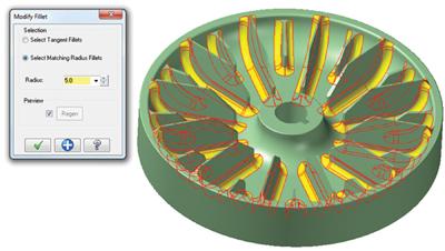
Use the new Modify Solid Fillet function to quickly change the radius of fillets in solid models that do not have any operation history. You can apply your changes to sets of tangential fillets or fillets with matching radii.
The new Solid Hole-Axis function creates axis lines in circular holes in solid bodies, with or without history. Hole-axis lines are created using your current system attribute settings (line size, color, etc.). You can also create related geometry (points and circles) using the options in the dialog box.
New controls have been added to the Xform Project dialog specifically for projecting onto a surface. Particularly useful when working with small parts, Mastercam now prompts you to increase your default tolerance to attain the best results. In addition, you can choose between projecting blended splines or attempting to match the number of source geometry pieces to the number of projected entities.
Contact Details
Related Glossary Terms
- computer numerical control ( CNC)
computer numerical control ( CNC)
Microprocessor-based controller dedicated to a machine tool that permits the creation or modification of parts. Programmed numerical control activates the machine’s servos and spindle drives and controls the various machining operations. See DNC, direct numerical control; NC, numerical control.
- computer-aided design ( CAD)
computer-aided design ( CAD)
Product-design functions performed with the help of computers and special software.
- fillet
fillet
Rounded corner or arc that blends together two intersecting curves or lines. In three dimensions, a fillet surface is a transition surface that blends together two surfaces.
- nonuniform rational B-splines ( NURBS)
nonuniform rational B-splines ( NURBS)
Type of curve or surface for which the difference between successive knots (parameter values) need not be expressed in uniform increments of 1. See B-spline.
- numerical control ( NC)
numerical control ( NC)
Any controlled equipment that allows an operator to program its movement by entering a series of coded numbers and symbols. See CNC, computer numerical control; DNC, direct numerical control.
- solid model
solid model
3-D model created using “building blocks.” This is the most accurate way of representing real-world objects in CAD.
- tolerance
tolerance
Minimum and maximum amount a workpiece dimension is allowed to vary from a set standard and still be acceptable.