
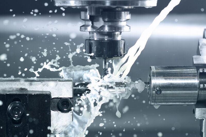
Safety in design is critical to CNC milling operations end products, as well as to the machine’s profitability. As the trajectory of today’s new milling technology trends toward machines producing extremely high speeds/high rpm within a smaller overall foot print–potential safety issues can’t be ignored. Loose tools moving fast could present the potential for a lot of damage to the machine and workpiece.
Indirect costs can run the gamut from damaged facilities or equipment. Currently there are no defined guidelines to address the potential hazards that small footprint/high RPM machines being introduced into the marketplace may present.
The bottom line is, everyone is looking to get more production per square inch and increase efficiency via heavy-duty, multiple-axis machines doing precision milling using less space. The daunting obligation and responsibility for both industry and machine builders is to keep machine operation as safe as possible, while achieving the consensus goal of optimizing mill productivity.
Without proper tools, milling machines can be a potentially dangerous threat at the forefront of this evolving safety climate. The retention knob is the main interface between the machine and the spindle and when exposed to severe conditions, failure of a standard retention knob can result in a tool breaking loose during a cutting operation. A tool, holder, or knob breaking loose from the spindle at such high speeds and spindle speeds produces a projectile that can damage the spindle, tool, holder, workpiece and workholding apparatus.
Recognizing the potential for machine spindle interface failure that these small-footprint/high-rpm machines represent, JM Performance Products Inc. offers its patented High Torque retention knobs. In addition to solving the critical “loose-tool” factor and preventing toolholder deformation, the patented design delivers inherent safety benefits that are vital to progressively addressing this velocity driven safety dilemma.
Most standard retention knobs are still being designed and manufactured to the standards put in place over 40 years ago–while the evolution of the tooling and the mills has been progressive and responsive. Even though it is a vital component in milling using V-Flange tooling, the retention knob has been largely over-looked in this evolution–including safety factors.
Extensive testing by JMPP has proven that standard design retention knobs often expand the toolholder, leading to excessive vibration, chatter and mill harmonics. In addition to affecting finishes, tolerances and tool life, this vibration and chatter, caused by a lack of concentricity, can be damaging to the spindle and the draw bar of the mill. With the advent of today’s fast, powerful, small-footprint machines, this damage can directly result in the high-risk, red-flag safety dangers associated with a tool breaking loose during a cutting operation. In essence, it’s a disaster waiting to happen because if anything breaks loose–it would essentially be like a missile coming off the machine!
In reality, any industry that depends on high-speed precision milling, whether for roughing simple and exotic materials to complex geometries and microparts, is going to face these tooling safety issues. By correcting the design flaw in the tooling, which is tool holder expansion, JMPP’s High Torque knobs overcome a myriad of issues industry wide in terms of production, time, tooling and safety.
One key factor in retention knob failure is the material strength–and JMPP is proactively migrating their 30 and 40 taper retention knobs from the traditional 8620H material to 9310H material, to ensure their durability and strength. The 9310H material offers 40 percent higher tensile strength than the 8620H material. Additionally, JMPP has reviewed the cross-sectional strength of the knobs and identified a design flaw. To correct this flaw, they are modifying the size of the coolant holes in many of their 30 and 40 taper knobs to increase this cross-sectional strength.
In addition to evolving material strength on knobs to optimize safety and overall production, JMPP also laser marks its parts–providing dating on each knob. The laser marked "date-in-service" feature, which includes a unique serial number for traceability, shows how long the knob has been in service.
This ensures safety as retention knobs are a perishable, consumable part–a typical retention knob is good for 1-3 years on a machine depending on how long the machine runs per day. The operator can simply enter the unique identifier serial number to show how long a knob has been in service and when a tool change should be made. Inspection of retention knobs during tool changes can reveal signs of diminished draw bar force. With spindle replacements costing $20,000 to upwards of $80,000, maintenance is critical.
Brother Industries, Ltd. is a leading multinational manufacturer of CNC drilling and tapping centers for the automobile, aerospace and medical industries. They identified the need to modify the standard used to manufacture their retention knobs, including the material tensile strength, to make them stronger to meet the machine’s manufacturing demands.
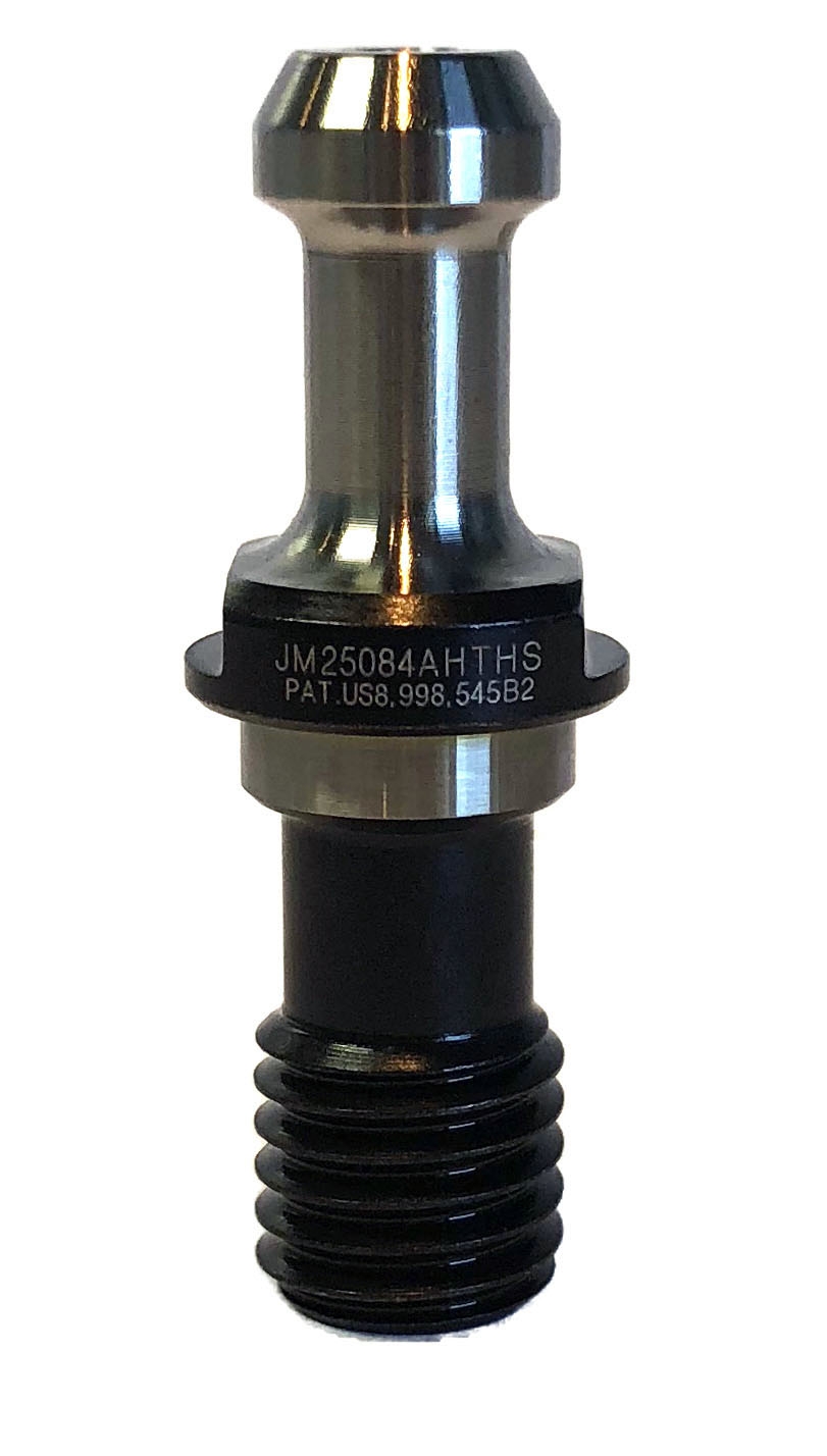
Using Brother’s modified spec for their BT30 retention knobs, JMPP quickly responded by introducing the JM25084ACHTHS (with coolant hole) and JM25084AHTHS (without coolant hole). These knobs incorporated all of Brother’s dimensional and radius requirements along with JMPP’s High Torque patented design features and higher tensile material.
JMPP’s engineering team is the only retention knob manufacturer of record to progressively respond to Brothers’ unique modification challenge with a customized solution, based on Brother’s revised specs and material, and incorporating their High Torque standard tolerances and design features.
After engineering modified the design which makes the knobs stronger for high RPM machines, used in the manufacture of small diameter parts, JMPP issued the following directive: Effective immediately for all Brother machines we need to be directing customers to use the JM25084AHTHS and JM25084ACHTHS instead of the current JM31109A, JM31109AHT and JM31109ACHT. The print provided by Brother notes changes to the knob on 4 dimensions and a material change not covered in MAS-P30T-2(30°).
Currently, JMPP has provided over 10,000 of the modified High Torque retention knobs to customers for their uniquely demanding high RPM machines, in addition to over 10,000 more of their standard High Torque knobs already in use.
The Brother example is part of a continuing trend of manufacturers being progressive in trying to push capacity while also thinking about safety. JMPP is also focusing on bringing safety issues to the forefront with leading manufacturers like Kitamura and its ultracompact (6’ wide x 9’7” deep) MYCENTER 30 taper horizontal machine, which offers rapid/cutting rates of 2,362 rpm on all axes. Given its speeds and size of tooling, JMPP views this as the ideal example of the trending combination that would benefit from their High Torque retention knobs–specifically their High Torque/High Speed JM32621HTHS.
While everyone is "squeezing size" as they strive to produce larger envelope parts on smaller machines, certain safety considerations must be addressed in this equation. Almost every kind of hazard can be found in a machine shop, and JMPP strives to be proactive in their approach to design, manufacturing, and key issues like how to increase speed rates safely that are facing the industry.
According to JMPP President John Stoneback, “It is our position that the industry as a whole needs to recognize the potential for machine spindle interface problems that these small footprint/high RPM machines represent. Our High Torque retention knobs have inherent design elements that meet these issues head-on and we’re hoping that machine builders, tooling builders, and distributors will join us in getting this vital message out.”
All JMPP retention knobs are manufactured and material sourced in the United States and made from hot rolled, 8620H, or Grade 9310-H fine-grain steel. H13 tool steel is also available upon request. They are shot peened to relieve stress, hard turned for superior fit-and-finish, and balanced by design. They meet all five World Standards: ANSI, JMTBA, ISO or DIN and JIS.
Contact Details
Related Glossary Terms
- centers
centers
Cone-shaped pins that support a workpiece by one or two ends during machining. The centers fit into holes drilled in the workpiece ends. Centers that turn with the workpiece are called “live” centers; those that do not are called “dead” centers.
- chatter
chatter
Condition of vibration involving the machine, workpiece and cutting tool. Once this condition arises, it is often self-sustaining until the problem is corrected. Chatter can be identified when lines or grooves appear at regular intervals in the workpiece. These lines or grooves are caused by the teeth of the cutter as they vibrate in and out of the workpiece and their spacing depends on the frequency of vibration.
- computer numerical control ( CNC)
computer numerical control ( CNC)
Microprocessor-based controller dedicated to a machine tool that permits the creation or modification of parts. Programmed numerical control activates the machine’s servos and spindle drives and controls the various machining operations. See DNC, direct numerical control; NC, numerical control.
- coolant
coolant
Fluid that reduces temperature buildup at the tool/workpiece interface during machining. Normally takes the form of a liquid such as soluble or chemical mixtures (semisynthetic, synthetic) but can be pressurized air or other gas. Because of water’s ability to absorb great quantities of heat, it is widely used as a coolant and vehicle for various cutting compounds, with the water-to-compound ratio varying with the machining task. See cutting fluid; semisynthetic cutting fluid; soluble-oil cutting fluid; synthetic cutting fluid.
- gang cutting ( milling)
gang cutting ( milling)
Machining with several cutters mounted on a single arbor, generally for simultaneous cutting.
- milling
milling
Machining operation in which metal or other material is removed by applying power to a rotating cutter. In vertical milling, the cutting tool is mounted vertically on the spindle. In horizontal milling, the cutting tool is mounted horizontally, either directly on the spindle or on an arbor. Horizontal milling is further broken down into conventional milling, where the cutter rotates opposite the direction of feed, or “up” into the workpiece; and climb milling, where the cutter rotates in the direction of feed, or “down” into the workpiece. Milling operations include plane or surface milling, endmilling, facemilling, angle milling, form milling and profiling.
- milling machine ( mill)
milling machine ( mill)
Runs endmills and arbor-mounted milling cutters. Features include a head with a spindle that drives the cutters; a column, knee and table that provide motion in the three Cartesian axes; and a base that supports the components and houses the cutting-fluid pump and reservoir. The work is mounted on the table and fed into the rotating cutter or endmill to accomplish the milling steps; vertical milling machines also feed endmills into the work by means of a spindle-mounted quill. Models range from small manual machines to big bed-type and duplex mills. All take one of three basic forms: vertical, horizontal or convertible horizontal/vertical. Vertical machines may be knee-type (the table is mounted on a knee that can be elevated) or bed-type (the table is securely supported and only moves horizontally). In general, horizontal machines are bigger and more powerful, while vertical machines are lighter but more versatile and easier to set up and operate.
- tapping
tapping
Machining operation in which a tap, with teeth on its periphery, cuts internal threads in a predrilled hole having a smaller diameter than the tap diameter. Threads are formed by a combined rotary and axial-relative motion between tap and workpiece. See tap.
- tensile strength
tensile strength
In tensile testing, the ratio of maximum load to original cross-sectional area. Also called ultimate strength. Compare with yield strength.
- toolholder
toolholder
Secures a cutting tool during a machining operation. Basic types include block, cartridge, chuck, collet, fixed, modular, quick-change and rotating.