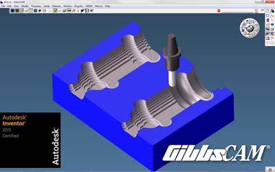
Gibbs and Associates announced that GibbsCAM has been certified for Autodesk Inventor 2013 3D mechanical design software under the Autodesk Inventor Certified Applications Program. Certification for Autodesk Inventor 2013 marks the twelfth consecutive year that GibbsCAM has been certified under the program, having achieved certification every year since the program began.
Autodesk Inventor software gives manufacturers the ability to digitally design, visualize and simulate how a product will work under real world conditions before it is built, which helps reduce cost and increase efficiency. GibbsCAM directly opens Autodesk Inventor part models, allowing CNC programmers and machinists to readily program machine tools from the models, to extend cost reduction and efficiency through the programming and machining processes. Certification demonstrates that the product is of high quality and up to date, and that it provides the highest level of interoperability with Autodesk Inventor software.
"We are pleased with Autodesk's recognition of our continued interoperability with Autodesk Inventor, which allows our joint customers to directly read models and assemblies into GibbsCAM," said Robb Weinstein, Senior Vice President of Sales and Strategic Planning of Gibbs and Associates. "Repeating our certification, year after year, provides assurance to these customers that they can continue to take advantage of the productivity they've gained from the combined products. It also assists and encourages our GibbsCAM resellers, worldwide, in providing uninterrupted support for Autodesk and its customers."
GibbsCAM offers seamless integration with Autodesk Inventor, by directly reading Autodesk Inventor IPT (part model) files, preserving all color information assigned within Inventor to provide continuity in recognizing and communicating part and feature attributes. Once machining processes are defined in GibbsCAM, they are automatically updated when the Inventor model is revised. GibbsCAM also directly reads AutoCAD DXF and DWG files, enabling use of part geometry to program machining processes.
"We are very pleased to have Gibbs and Associates renew Inventor certification for GibbsCAM," said Jim Quanci, director of the Autodesk Developer Network at Autodesk. "Their constant dedication to interoperability with Autodesk Inventor, ease of use, and support for manufacturing customers is exemplary. We are proud to have companies like Gibbs and Associates as partners in delivering flexible, easy-to-use, and extensible applications to our manufacturing customers."
GibbsCAM has an easy-to-use and simple-to-navigate interface, with language and icons familiar to programmers and machinists, allowing its users to quickly take advantage of its powerful capabilities, from minimizing the learning curve, to making manufacturing engineering tasks and production machining extremely intuitive and efficient. GibbsCAM provides the capability to program the most complex machining processes, and the flexibility to allow user-preferred approaches to machining, with options that are logical to programmers.
GibbsCAM's full associativity of geometry, processes and toolpaths easily accommodates updates to Autodesk Inventor part geometry and process parameters. CNC programmers can quickly optimize parts for machining and program machine tools to make the parts, whether they have simple geometry needing only 2-axis turning or 2.5-axis milling, or complex geometry requiring the latest 5-axis machining centers, MTMs or Swiss-style turning centers. GibbsCAM verifies toolpaths with gouge detection and interference checking, and enables additional testing and prove-out with a dynamic display of all moving components of a machine tool as it makes a part. These, and many other features of GibbsCAM help manufacturers eliminate scrap, reduce cycle times, and maximize efficiency, safety and profits.
In addition to its perennial certification of GibbsCAM for Autodesk Inventor, Gibbs and Associates is an authorized member of the Autodesk Developer Network and is an Autodesk Authorized Independent Software Vendor.
Contact Details
Related Glossary Terms
- centers
centers
Cone-shaped pins that support a workpiece by one or two ends during machining. The centers fit into holes drilled in the workpiece ends. Centers that turn with the workpiece are called “live” centers; those that do not are called “dead” centers.
- computer numerical control ( CNC)
computer numerical control ( CNC)
Microprocessor-based controller dedicated to a machine tool that permits the creation or modification of parts. Programmed numerical control activates the machine’s servos and spindle drives and controls the various machining operations. See DNC, direct numerical control; NC, numerical control.
- gang cutting ( milling)
gang cutting ( milling)
Machining with several cutters mounted on a single arbor, generally for simultaneous cutting.
- inches per tooth ( ipt)
inches per tooth ( ipt)
Linear distance traveled by the cutter during the engagement of one tooth. Although the milling cutter is a multi-edge tool, it is the capacity of each individual cutting edge that sets the limit of the tool, defined as: ipt = ipm/number of effective teeth 5 rpm or ipt = ipr/number of effective teeth. Sometimes referred to as the chip load.
- milling
milling
Machining operation in which metal or other material is removed by applying power to a rotating cutter. In vertical milling, the cutting tool is mounted vertically on the spindle. In horizontal milling, the cutting tool is mounted horizontally, either directly on the spindle or on an arbor. Horizontal milling is further broken down into conventional milling, where the cutter rotates opposite the direction of feed, or “up” into the workpiece; and climb milling, where the cutter rotates in the direction of feed, or “down” into the workpiece. Milling operations include plane or surface milling, endmilling, facemilling, angle milling, form milling and profiling.
- turning
turning
Workpiece is held in a chuck, mounted on a face plate or secured between centers and rotated while a cutting tool, normally a single-point tool, is fed into it along its periphery or across its end or face. Takes the form of straight turning (cutting along the periphery of the workpiece); taper turning (creating a taper); step turning (turning different-size diameters on the same work); chamfering (beveling an edge or shoulder); facing (cutting on an end); turning threads (usually external but can be internal); roughing (high-volume metal removal); and finishing (final light cuts). Performed on lathes, turning centers, chucking machines, automatic screw machines and similar machines.

