Feeler Machines

April 01, 2011

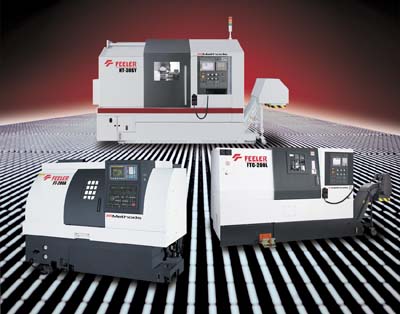
Methods Machine Tools Inc. has introduced FEELER Milling Lathes and Turning Centers featuring extensive design and engineering by Methods. FEELER Lathes and Turning Centers are backed by Methods' application expertise, support, and extensive network of technology centers. The Methods-FEELER CNC Lathes and Turning Centers include the HT-Series, FTC-Series and FT-Series.

"To meet our customers' unique requirements, Methods has incorporated several different designs and options in the new FEELER milling lathes and turning centers," said Mr. Paul Hurtig, FEELER Product Manager, Methods Machine Tools.

The FEELER HT-Series High Performance Milling Lathes are offered in three configurations including an HT-30MC power milling turret machine, an HT-30Y model with a power milling turret and Y-axis and an HT-30SY machine featuring a power milling turret, Y-axis and a sub-spindle Each HT-Series lathe features a 3,500 rpm, 30 HP spindle with chuck diameter of 10". The HT-30SY also offers a 6,000 rpm, 15 HP sub-spindle with a 6" (170mm) chuck diameter and a bar capacity of 1.7" (44mm). X-Axis travel is 7" + 3.2" (178mm + 82mm) and Z-Axis travel is 31.3" (795mm) in each of the HT-Series machines. The HT-30Y and HR-30SY machines also offer a Y-Axis travel of 3.9". The HT-Series features a 30 degree slant bed with hand scraped slideway surfaces. Maximum turning diameter is 14" (356mm) and maximum turning length is 27.75" (705mm). A 12-position power turret with milling capability and FANUC 18i-TB control are standard.

Related Glossary Terms

  • centers

    centers

    Cone-shaped pins that support a workpiece by one or two ends during machining. The centers fit into holes drilled in the workpiece ends. Centers that turn with the workpiece are called “live” centers; those that do not are called “dead” centers.

  • chuck

    chuck

    Workholding device that affixes to a mill, lathe or drill-press spindle. It holds a tool or workpiece by one end, allowing it to be rotated. May also be fitted to the machine table to hold a workpiece. Two or more adjustable jaws actually hold the tool or part. May be actuated manually, pneumatically, hydraulically or electrically. See collet.

  • computer numerical control ( CNC)

    computer numerical control ( CNC)

    Microprocessor-based controller dedicated to a machine tool that permits the creation or modification of parts. Programmed numerical control activates the machine’s servos and spindle drives and controls the various machining operations. See DNC, direct numerical control; NC, numerical control.

  • gang cutting ( milling)

    gang cutting ( milling)

    Machining with several cutters mounted on a single arbor, generally for simultaneous cutting.

  • lathe

    lathe

    Turning machine capable of sawing, milling, grinding, gear-cutting, drilling, reaming, boring, threading, facing, chamfering, grooving, knurling, spinning, parting, necking, taper-cutting, and cam- and eccentric-cutting, as well as step- and straight-turning. Comes in a variety of forms, ranging from manual to semiautomatic to fully automatic, with major types being engine lathes, turning and contouring lathes, turret lathes and numerical-control lathes. The engine lathe consists of a headstock and spindle, tailstock, bed, carriage (complete with apron) and cross slides. Features include gear- (speed) and feed-selector levers, toolpost, compound rest, lead screw and reversing lead screw, threading dial and rapid-traverse lever. Special lathe types include through-the-spindle, camshaft and crankshaft, brake drum and rotor, spinning and gun-barrel machines. Toolroom and bench lathes are used for precision work; the former for tool-and-die work and similar tasks, the latter for small workpieces (instruments, watches), normally without a power feed. Models are typically designated according to their “swing,” or the largest-diameter workpiece that can be rotated; bed length, or the distance between centers; and horsepower generated. See turning machine.

  • milling

    milling

    Machining operation in which metal or other material is removed by applying power to a rotating cutter. In vertical milling, the cutting tool is mounted vertically on the spindle. In horizontal milling, the cutting tool is mounted horizontally, either directly on the spindle or on an arbor. Horizontal milling is further broken down into conventional milling, where the cutter rotates opposite the direction of feed, or “up” into the workpiece; and climb milling, where the cutter rotates in the direction of feed, or “down” into the workpiece. Milling operations include plane or surface milling, endmilling, facemilling, angle milling, form milling and profiling.

  • turning

    turning

    Workpiece is held in a chuck, mounted on a face plate or secured between centers and rotated while a cutting tool, normally a single-point tool, is fed into it along its periphery or across its end or face. Takes the form of straight turning (cutting along the periphery of the workpiece); taper turning (creating a taper); step turning (turning different-size diameters on the same work); chamfering (beveling an edge or shoulder); facing (cutting on an end); turning threads (usually external but can be internal); roughing (high-volume metal removal); and finishing (final light cuts). Performed on lathes, turning centers, chucking machines, automatic screw machines and similar machines.