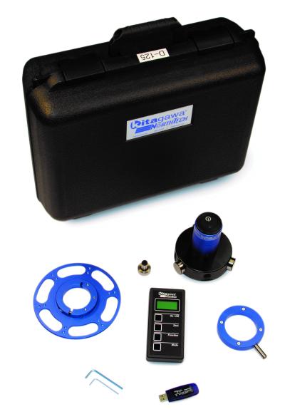
Kitagawa NorthTech Inc. introduces its Digital Grip Force Analyzer software and kit (PC version) for machine tool users and machine shops. The gripping force provided by the workholding and chucking solution is paramount to successfully machining high quality parts. It is often the single largest reason why a machine tool user encounters a variety of issues hindering productivity, performance, reliability and accuracy of the workholding.
One common issue is parts slipping in the chuck, which in turn reduces cycle times, productivity and profits and causes safety issues. Determining gripping force of the workholding in CNC lathes and turning centers has always been difficult for machine tool users, until now. The new software and kit from Kitagawa NorthTech allows users to easily, accurately and quickly analyze and measure grip force performance of their CNC lathes and turning centers via a desktop PC, laptop or tablet. If gripping force issues exist, users can take proactive and corrective measures to identify and solve these problems with the Digital Grip Force Analyzer software and kit from Kitagawa NorthTech. Users can download a free version at: http://kitagawa.com/chucks/chuck-accessories-chucks/wireless-grip-force-meter/.
In addition to the software package, Kitagawa NorthTech provides a total solution for machine tool users to simplify performing process and service diagnostics on the machining equipment. The Digital Grip Force Analyzer software PC version from Kitagawa NorthTech comes bundled as a complete kit with rugged carrying case, super powerful Bluetooth dongle loaded with PC analyzer software, digital load meter and the traditional handheld pendant for manual diagnostics, testing and measurement. The company offers the complete kit available for purchase from a distributor or channel partner. It is suggested that every machine shop can benefit from this indispensable tool and should have at least one or two Kitagawa’s Digital Grip Force Analyzer software kits available for everyday testing, monitoring and troubleshooting.
The Digital Grip Force Analyzer software is easily installed onto the PC or laptop via the super powerful Bluetooth dongle. Once installed, the user clicks the Bluetooth icon on the laptop screen and then pushes the Bluetooth icon on the Kitagawa Digital Grip Force Load Meter to initiate connectivity. The Digital Load Meter will start flashing, and once found by the laptop it will quickly then connect as indicated via the button on the screen that was flashing red, is now flashing green. This is confirmation that the Digital Grip Force Load Meter is successfully connected to the laptop via the USB.
A ring magnet is mounted to the mag based and centered on the load meter in the CNC machine. This communicates the tachometer on the machine is now active and the user can proceed with testing their lathe or turning centers. Once the user inputs the required data and commences run test, the software will compile a G-code program to run the test on the machine. Once the test has run and is completed the software will then plot on the PC screen the actual gripping force of the machine at all RPMs you have entered. It’s that simple.
This is the software’s main screen for operators with easy to navigate tabs, which includes machine parameters, settings, diagnostics and an about section tab.
Machine parameters tab lets users input information regarding the specific machine and application, such as number of spindles, gear pages, maximum RPM settings, and G code addresses for dwells.
The settings tab displays grip force in newtons, kilograms force or pound force. It also has settings to disable or enable data collection and create and save a sensor log file.
This diagnostics tab provides users the actual live reading of the software connected to the sensor. This is where communication from the sensor and software takes place.
Contact Details
Related Glossary Terms
- centers
centers
Cone-shaped pins that support a workpiece by one or two ends during machining. The centers fit into holes drilled in the workpiece ends. Centers that turn with the workpiece are called “live” centers; those that do not are called “dead” centers.
- chuck
chuck
Workholding device that affixes to a mill, lathe or drill-press spindle. It holds a tool or workpiece by one end, allowing it to be rotated. May also be fitted to the machine table to hold a workpiece. Two or more adjustable jaws actually hold the tool or part. May be actuated manually, pneumatically, hydraulically or electrically. See collet.
- computer numerical control ( CNC)
computer numerical control ( CNC)
Microprocessor-based controller dedicated to a machine tool that permits the creation or modification of parts. Programmed numerical control activates the machine’s servos and spindle drives and controls the various machining operations. See DNC, direct numerical control; NC, numerical control.
- lathe
lathe
Turning machine capable of sawing, milling, grinding, gear-cutting, drilling, reaming, boring, threading, facing, chamfering, grooving, knurling, spinning, parting, necking, taper-cutting, and cam- and eccentric-cutting, as well as step- and straight-turning. Comes in a variety of forms, ranging from manual to semiautomatic to fully automatic, with major types being engine lathes, turning and contouring lathes, turret lathes and numerical-control lathes. The engine lathe consists of a headstock and spindle, tailstock, bed, carriage (complete with apron) and cross slides. Features include gear- (speed) and feed-selector levers, toolpost, compound rest, lead screw and reversing lead screw, threading dial and rapid-traverse lever. Special lathe types include through-the-spindle, camshaft and crankshaft, brake drum and rotor, spinning and gun-barrel machines. Toolroom and bench lathes are used for precision work; the former for tool-and-die work and similar tasks, the latter for small workpieces (instruments, watches), normally without a power feed. Models are typically designated according to their “swing,” or the largest-diameter workpiece that can be rotated; bed length, or the distance between centers; and horsepower generated. See turning machine.
- turning
turning
Workpiece is held in a chuck, mounted on a face plate or secured between centers and rotated while a cutting tool, normally a single-point tool, is fed into it along its periphery or across its end or face. Takes the form of straight turning (cutting along the periphery of the workpiece); taper turning (creating a taper); step turning (turning different-size diameters on the same work); chamfering (beveling an edge or shoulder); facing (cutting on an end); turning threads (usually external but can be internal); roughing (high-volume metal removal); and finishing (final light cuts). Performed on lathes, turning centers, chucking machines, automatic screw machines and similar machines.

