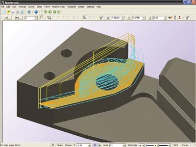
Mastercam from CNC Software Inc. is known for powerful NC programming, but it also delivers a suite of shop-tested design tools including 3D surfacing and solids. The streamlined CAD engine makes design work easier than ever before.
Mastercam Design streamlines modeling and editing geometry. It also supports advanced geometry creation, including NURBS curves and surfaces, 2D and 3D associative dimensioning, surface extension, blending, trimming, splitting, variable filleting, solid modeling, hybrid modeling, and more.
A few new enhancements to Mastercam Design X6 are:
Region Chaining — Mastercam's 2D Dynamic Milling is greatly simplified with the introduction of Region Chaining. You now define the area for a 2D dynamic milling toolpath by simply selecting the face to be machined and face to be avoided. Mastercam treats the selections (even on open pockets) as complete machining chains.
Intersecting and Trimming Solid Edges — Mastercam automatically recognizes intersections between wireframe geometry and solid edges.
Enhanced Solid Trim to Surface — New options give you even greater control over your solid/surface trim results.
Solid History Removal — Mastercam lets you strip the list of operations or features from a solid model, leaving it as a "brick" to prevent changes and protect your model. Transform (Xform) Fit Mastercam can "nest" geometry along a vector. This feature can be particularly helpful when you are fitting parts between clamps and fixtures.
Contact Details
Related Glossary Terms
- computer numerical control ( CNC)
computer numerical control ( CNC)
Microprocessor-based controller dedicated to a machine tool that permits the creation or modification of parts. Programmed numerical control activates the machine’s servos and spindle drives and controls the various machining operations. See DNC, direct numerical control; NC, numerical control.
- computer-aided design ( CAD)
computer-aided design ( CAD)
Product-design functions performed with the help of computers and special software.
- gang cutting ( milling)
gang cutting ( milling)
Machining with several cutters mounted on a single arbor, generally for simultaneous cutting.
- milling
milling
Machining operation in which metal or other material is removed by applying power to a rotating cutter. In vertical milling, the cutting tool is mounted vertically on the spindle. In horizontal milling, the cutting tool is mounted horizontally, either directly on the spindle or on an arbor. Horizontal milling is further broken down into conventional milling, where the cutter rotates opposite the direction of feed, or “up” into the workpiece; and climb milling, where the cutter rotates in the direction of feed, or “down” into the workpiece. Milling operations include plane or surface milling, endmilling, facemilling, angle milling, form milling and profiling.
- nonuniform rational B-splines ( NURBS)
nonuniform rational B-splines ( NURBS)
Type of curve or surface for which the difference between successive knots (parameter values) need not be expressed in uniform increments of 1. See B-spline.
- numerical control ( NC)
numerical control ( NC)
Any controlled equipment that allows an operator to program its movement by entering a series of coded numbers and symbols. See CNC, computer numerical control; DNC, direct numerical control.
- solid model
solid model
3-D model created using “building blocks.” This is the most accurate way of representing real-world objects in CAD.
- toolpath( cutter path)
toolpath( cutter path)
2-D or 3-D path generated by program code or a CAM system and followed by tool when machining a part.
