3D is the trend in measuring technology. A number of geometries can only be captured and evaluated in 3D, and they are also a lot closer to the construction drawings which are prepared in 3D. ZOLLER has intelligently adopted this trend and presents visionary options in metrology with the five-axis CNC machine >>3dCheck<<.
ZOLLER enables the fully automatic measurement and evaluation process for all current standard geometries of round tools. ZOLLER, known for user-friendly advanced technology, has also simplified the approach for the user, in comparison to other systems available on the market.
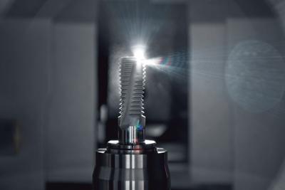
The digitalization of workpieces is effortless due to the calibrated linkage between the transmitted light image processing and the 3D sensor of the measuring machine.
Aligning the workpieces and determining the significant geometric characteristics is performed automatically, as well as the positioning of the transmitted light image processing to the 3D sensor. In the next step, 3D digitalization of the workpiece surface is performed via a measuring plan which was filed once for the tool via the graphic ZOLLER >>pilot<< interface. The 3D measurement data set is evaluated automatically after digitalization.
The compact design of the ZOLLER's machine was developed specifically for the 3D digitalization application field. The universal machine mechanics offer a broad spectrum of applications and ensure optimal positioning of the measuring sensor in relation to the surface of the workpiece. The universal tool holding fixture provides the user with high precision clamping of the workpieces. The highly detailed display of the workpiece geometry is enabled by the high lateral resolution of the sensor.
In conjunction with a specially developed calibration process, the solid machine design allows complete digitalization of workpieces from different sensor perspectives. These are fed back automatically into a uniform workpiece coordinate system without requiring the elaborate use of reference measuring points or the mechanical mounting of backdrops. This results in considerable time savings when preparing workpieces for measuring. Feeding the various measuring perspectives and positions into a uniform workpiece coordinate system is performed automatically.
A topographic target/actual comparison and optional cross sections allow a complete analysis of the workpieces at a glance. The analysis of the 3D measurement data is another major advantage compared with existing measurement methods. They can be exported in a standardized format and can be processed further in CAD or in 3D analysis applications.
Contact Details
Related Glossary Terms
- calibration
calibration
Checking measuring instruments and devices against a master set to ensure that, over time, they have remained dimensionally stable and nominally accurate.
- computer numerical control ( CNC)
computer numerical control ( CNC)
Microprocessor-based controller dedicated to a machine tool that permits the creation or modification of parts. Programmed numerical control activates the machine’s servos and spindle drives and controls the various machining operations. See DNC, direct numerical control; NC, numerical control.
- computer-aided design ( CAD)
computer-aided design ( CAD)
Product-design functions performed with the help of computers and special software.
- fixture
fixture
Device, often made in-house, that holds a specific workpiece. See jig; modular fixturing.
- metrology
metrology
Science of measurement; the principles on which precision machining, quality control and inspection are based. See precision machining, measurement.