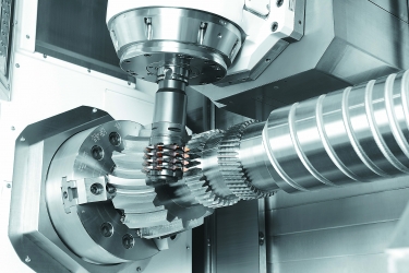
Precise synchronization between the cutter and spindle is needed for any gear-machining operation. Image courtesy of Mazak
Perhaps you already own a multitask machine or a mill/turn lathe. Perhaps you’ve considered investing in one. Whatever the case, here’s yet another way that these machines can add value and flexibility to any job shop or discrete manufacturing company: gear hobbing.
Hobbing, like most gear-making operations, is a complex process. It uses a rotating drum-shaped cutter that, depending on the gear type, is either held parallel to the workpiece centerline or tipped at a slight angle. As the hob rotates, the machine is fed in the longitudinal axis into the workpiece, which rotates in the same direction but at a slower rpm. It is a single-pass process and, in terms of multitaskers and mill/turn lathes, primarily for external gear production.
Multi-Options
As you might have guessed, hobbing requires specialized cutting tools called hobs. It also demands accurate synchronization between the rotating workpiece and cutter and a working knowledge of terms like root circle, pressure angle and module. This is why most shops have long subcontracted their gear-cutting needs to specialty houses, which have the equipment and tools necessary to perform such esoteric work.
Not anymore. Thanks to increasingly capable CNC machines and on-board programming software that tames even the gnarliest of gear forms, machine shops everywhere are performing their low- to medium-volume gear work in-house. One example is the Integrex AG series multitask machine from Mazak Corp. Mike Finn, senior applications development engineer, said the unit has several additional features that allow it to perform at a higher level than a standard Integrex.
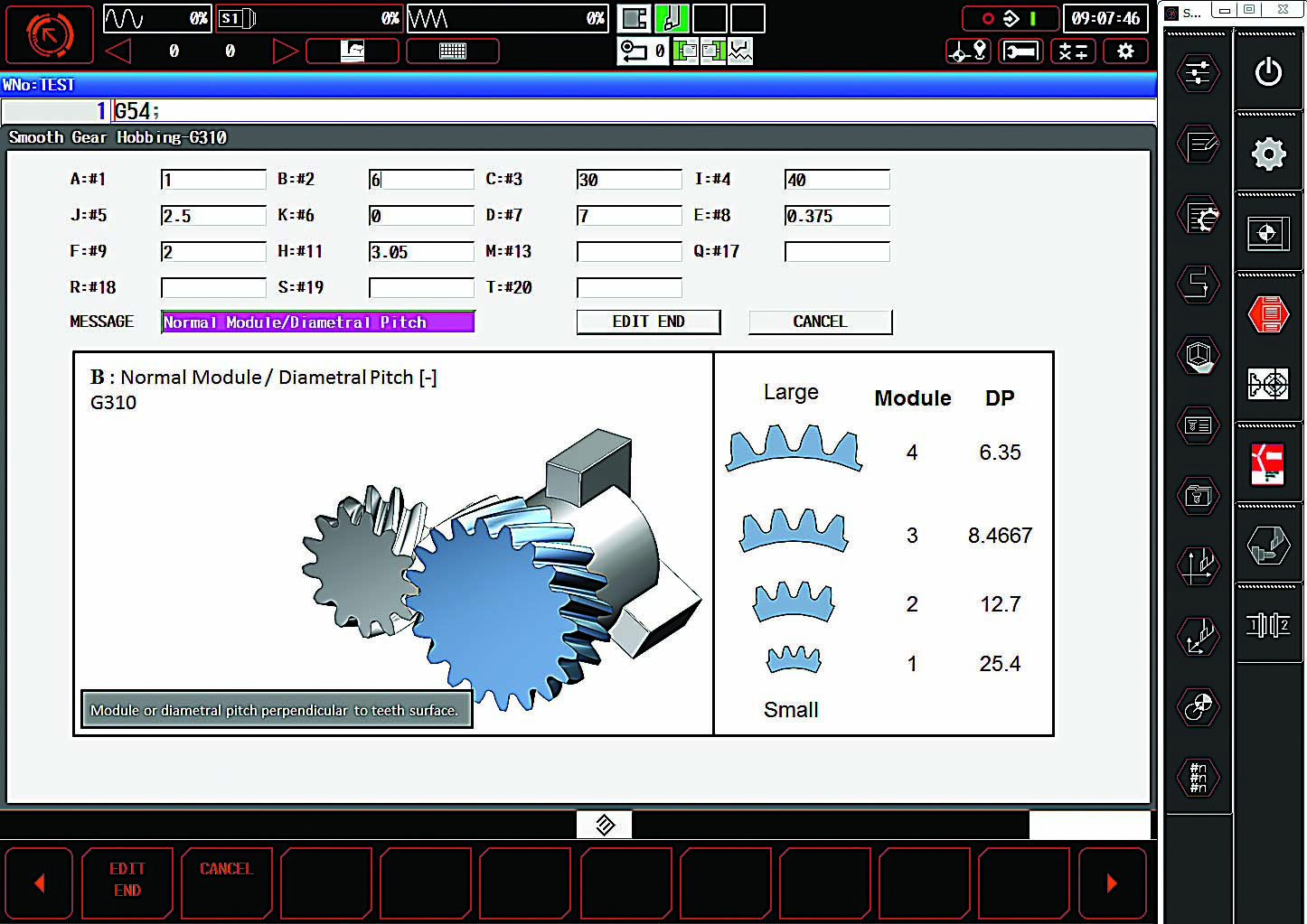
“Because synchronization is critical when hobbing, we’ve added scale feedback to the Z-axis and the milling spindle,” he said. “There’s also a software package included on the Integrex AG machines titled Smooth Gear that lets you plug in values, such as diametral pitch, helix angle, pressure angle, cutter diameter and various gear form information, and the control will make the program for you. There are three modules to serve milling, hobbing and power skiving gear-cutting strategies.”
Splines are among the many gear forms produced on multitask and mill/turn machines. Image courtesy of Okuma America
The Florence, Kentucky, machine builder isn’t alone. Hoffman Estates, Illinois-based DMG Mori USA Inc. offers similar gear-hobbing options, or Technology Cycles, on its NLX, CTX and NZX series lathes. Okuma America Corp., Charlotte, North Carolina, has gear packages for the company’s Multus multitask machines, as well as several of its mill/turn centers. Each uses the same hobs found on any comparable hobbing machine, and each is capable of producing a variety of high-quality gears and splines, although at a slightly slower rate than a dedicated hobber.
Why Go Slow?
No machinist or shop owner likes to hear the words “slower rate” used in any sentence. And because users need dedicated tools anyway, many people might suggest that it makes more sense to purchase a used, far less expensive mechanical hobbing machine and stick it in a corner for occasional gear jobs rather than waste valuable multitasking time on a suboptimal machining process.
But not so fast. Multitask machines and mill/turn lathes are known for their ability to reduce part handling and work in process while increasing part quality, and geared parts are no exception. And as far as using a decades-old hobbing machine goes, it’s difficult enough to find qualified CNC machinists.
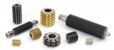
The hobs used on CNC lathes are no different from those used on dedicated hobbing machines. Image courtesy of Star Su
“Unless you have high production, you’re probably not going to buy a gear-cutting machine, new or used, because operating one calls for a very specialized skill set,” said Kevin Kraieski, senior application engineer at Okuma America. “Hobbing and indeed any kind of gear making is just so much easier on a multitasking machine. Also, companies generally want to integrate their processes into as few operations as possible. That’s the beauty of any multitasker or mill/turn.”
Tooling Up
Easy or not, there’s still plenty to know before embarking on any gear-making project. Robert Smiley, applications engineer at DMG Mori USA’s 5-Axis Center of Excellence in Hoffman Estates, said the company’s Technology Cycles make the programming aspect of hobbing easier. But he said there’s also machine-dependent tooling to consider.
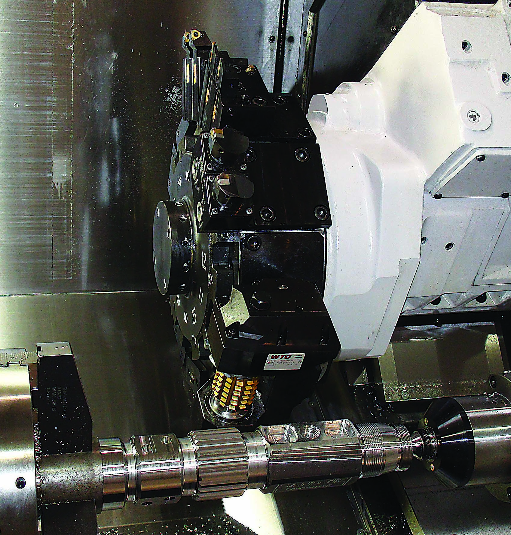
“On a turret-based lathe,” he said, “you’ll need to purchase a special hob holder from someone like WTO or MD Tooling, which mounts on the turret and supports the cutter from both ends. For a multitasking machine, you would most likely opt for a spindle-mounted hob, probably using a Capto or HSK toolholder for the greatest rigidity.”
Compared with many machining processes, cutting forces are relatively high with hobbing. So it’s easy to argue that because a turret-mounted tool has dual support and therefore greater rigidity, this is the clear path. However, dual support means greater potential for interference with the toolholder, making the ends of a fairly expensive cutting tool harder to reach. Also, a turret-driven toolholder’s available torque is a fraction of the torque from a multitasker’s milling spindle, reducing some of the rigidity gains.
Slightly greater tool deflection, however, is a fairly small price to pay for access to the entire length of the tool. This is the case with spindle-mounted hobs, which as a rule provide greater flexibility and tool life despite the need for less aggressive cutting parameters. Some machine tool builders have even added automatic shifting capabilities so tool wear can be spread across all the hob’s teeth.
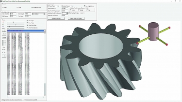
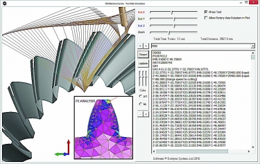
Dontyne Systems’ Gear Production Suite is advertised as a complete gear manufacturing solution, including design, machining and measurement. Image courtesy of Dontyne Systems
Hob selection is also important. Tom Ware, product manager for gear tools at Star SU LLC, Hoffman Estates, said myriad hob styles, coatings, tooth geometries and base materials are available.
“Choosing a hob is really no different than choosing any other cutting tool in that you have to pick the appropriate substrate and coating based on the workpiece material, production quantities and budget,” he said. “Whichever tool you select, though, just know that each form is unique, and you will need a different hob for each gear.”
The Waiting Game
Buying multiple different hobs is a bummer for some people. Although a powder metal or HSS cutter is less expensive than one made of carbide, it still costs hundreds of dollars—sometimes way more. Aside from a generous tool budget, good planning is needed because lead times for even a standard hob are best measured in weeks and months.
An alternative to waiting for a special cutter is to mill the gear profile using a ballnose cutter, an operation that many machine tool builders support. This can be accomplished on a multitasker and some mill/turn machines, but it’s easy on a 5-axis machining center. Milling individual teeth in this manner, if the most flexible approach, does rank among the slowest of all gear production methods.
Given the right machine, software and cutting tools, even complex parts like this one can be“done in one.” Image courtesy of Mazak
Despite some apparent, though often negligible, drawbacks, growth in this area is high. Each machine builder source said it has seen great interest in hobbing in recent years, with hundreds of gear-making control packages sold. A variety of such packages and software programs are available, including gear hobbing; power skiving, which often is used for internal gears; and milling.
Aside from the control software, some builders offer probing cycles for in-process part measurement. This can be a big help to newcomers who are learning not only how to make gears but how to measure them. Properly executed, the gears produced on multitaskers and mill/turn centers are very accurate, with American Gear Manufacturers Association ratings in the range of eight to 10 (12 being highest).
Take It to the Limit
Mike Fish, co-director of Dontyne Systems Ltd., a software developer in Newcastle Upon Tyne, England, that specializes in gear manufacturing, has a slightly different take on hobbing. He said there’s much more to making gears than cutters, machine tools and easy-to-use programming cycles. There’s also gear design.
“Unless you specialize in gear making, it can be difficult to understand what effect even very small deviations in the manufacturing can have on gear accuracy,” he said. “Based on the application, a gear’s tooth form can vary, and micron-sized adjustments are often applied to optimize performance. This is why our company focused its efforts on a closed-loop system, one that helps you design the gear; machine it precisely despite distortions, deflections and tool wear; and verify the results with the inspection machine.”
The company’s Gear Production Suite or a similar software package is a necessity for people designing and producing their own gears, but part manufacturers might question the need and say that’s what the control option is for. Yet shops that arm themselves with the best tools possible are most successful, especially with a complex undertaking like gear making, said Rich Easley, North American business manager for Dontyne Systems.
“The real power behind a system like this is that it links the design process to manufacturing,” he said. “It offers offline simulations for various gear-making processes, including hobbing, grinding, shaping, shaving and skiving. It provides cutting paths and tool design functions for CNC machinery, as well as inspection files for gear-checking machines, CMMs and in-process probing systems. It can help a shop utilize their existing tooling to produce prototypes or small-batch gears quickly and at low cost and allows a CNC to produce very challenging gears—spiral bevels, for instance—rather than using dedicated equipment. And perhaps most importantly, it opens the door for anyone that wants to pursue additional gear-making opportunities.”
Contact Details
Contact Details

Contact Details

Related Glossary Terms
- centers
centers
Cone-shaped pins that support a workpiece by one or two ends during machining. The centers fit into holes drilled in the workpiece ends. Centers that turn with the workpiece are called “live” centers; those that do not are called “dead” centers.
- closed-loop system
closed-loop system
CNC system in which the program output, or the distance the slide moves, is measured and compared to the program input. The system automatically adjusts the output to be the same as the input.
- computer numerical control ( CNC)
computer numerical control ( CNC)
Microprocessor-based controller dedicated to a machine tool that permits the creation or modification of parts. Programmed numerical control activates the machine’s servos and spindle drives and controls the various machining operations. See DNC, direct numerical control; NC, numerical control.
- gang cutting ( milling)
gang cutting ( milling)
Machining with several cutters mounted on a single arbor, generally for simultaneous cutting.
- grinding
grinding
Machining operation in which material is removed from the workpiece by a powered abrasive wheel, stone, belt, paste, sheet, compound, slurry, etc. Takes various forms: surface grinding (creates flat and/or squared surfaces); cylindrical grinding (for external cylindrical and tapered shapes, fillets, undercuts, etc.); centerless grinding; chamfering; thread and form grinding; tool and cutter grinding; offhand grinding; lapping and polishing (grinding with extremely fine grits to create ultrasmooth surfaces); honing; and disc grinding.
- helix angle
helix angle
Angle that the tool’s leading edge makes with the plane of its centerline.
- high-speed steels ( HSS)
high-speed steels ( HSS)
Available in two major types: tungsten high-speed steels (designated by letter T having tungsten as the principal alloying element) and molybdenum high-speed steels (designated by letter M having molybdenum as the principal alloying element). The type T high-speed steels containing cobalt have higher wear resistance and greater red (hot) hardness, withstanding cutting temperature up to 1,100º F (590º C). The type T steels are used to fabricate metalcutting tools (milling cutters, drills, reamers and taps), woodworking tools, various types of punches and dies, ball and roller bearings. The type M steels are used for cutting tools and various types of dies.
- lapping compound( powder)
lapping compound( powder)
Light, abrasive material used for finishing a surface.
- lathe
lathe
Turning machine capable of sawing, milling, grinding, gear-cutting, drilling, reaming, boring, threading, facing, chamfering, grooving, knurling, spinning, parting, necking, taper-cutting, and cam- and eccentric-cutting, as well as step- and straight-turning. Comes in a variety of forms, ranging from manual to semiautomatic to fully automatic, with major types being engine lathes, turning and contouring lathes, turret lathes and numerical-control lathes. The engine lathe consists of a headstock and spindle, tailstock, bed, carriage (complete with apron) and cross slides. Features include gear- (speed) and feed-selector levers, toolpost, compound rest, lead screw and reversing lead screw, threading dial and rapid-traverse lever. Special lathe types include through-the-spindle, camshaft and crankshaft, brake drum and rotor, spinning and gun-barrel machines. Toolroom and bench lathes are used for precision work; the former for tool-and-die work and similar tasks, the latter for small workpieces (instruments, watches), normally without a power feed. Models are typically designated according to their “swing,” or the largest-diameter workpiece that can be rotated; bed length, or the distance between centers; and horsepower generated. See turning machine.
- machining center
machining center
CNC machine tool capable of drilling, reaming, tapping, milling and boring. Normally comes with an automatic toolchanger. See automatic toolchanger.
- milling
milling
Machining operation in which metal or other material is removed by applying power to a rotating cutter. In vertical milling, the cutting tool is mounted vertically on the spindle. In horizontal milling, the cutting tool is mounted horizontally, either directly on the spindle or on an arbor. Horizontal milling is further broken down into conventional milling, where the cutter rotates opposite the direction of feed, or “up” into the workpiece; and climb milling, where the cutter rotates in the direction of feed, or “down” into the workpiece. Milling operations include plane or surface milling, endmilling, facemilling, angle milling, form milling and profiling.
- milling machine ( mill)
milling machine ( mill)
Runs endmills and arbor-mounted milling cutters. Features include a head with a spindle that drives the cutters; a column, knee and table that provide motion in the three Cartesian axes; and a base that supports the components and houses the cutting-fluid pump and reservoir. The work is mounted on the table and fed into the rotating cutter or endmill to accomplish the milling steps; vertical milling machines also feed endmills into the work by means of a spindle-mounted quill. Models range from small manual machines to big bed-type and duplex mills. All take one of three basic forms: vertical, horizontal or convertible horizontal/vertical. Vertical machines may be knee-type (the table is mounted on a knee that can be elevated) or bed-type (the table is securely supported and only moves horizontally). In general, horizontal machines are bigger and more powerful, while vertical machines are lighter but more versatile and easier to set up and operate.
- parallel
parallel
Strip or block of precision-ground stock used to elevate a workpiece, while keeping it parallel to the worktable, to prevent cutter/table contact.
- pitch
pitch
1. On a saw blade, the number of teeth per inch. 2. In threading, the number of threads per inch.
- shaping
shaping
Using a shaper primarily to produce flat surfaces in horizontal, vertical or angular planes. It can also include the machining of curved surfaces, helixes, serrations and special work involving odd and irregular shapes. Often used for prototype or short-run manufacturing to eliminate the need for expensive special tooling or processes.
- toolholder
toolholder
Secures a cutting tool during a machining operation. Basic types include block, cartridge, chuck, collet, fixed, modular, quick-change and rotating.
Author

Kip Hanson is a contributing editor for Cutting Tool Engineering magazine. Contact him by phone at (520) 548-7328 or via e-mail at [email protected].
Contributors
DMG Mori USA Inc.
847-593-5400
www.dmgmori.com
Dontyne Systems Ltd.
+44 191 206 4021
www.dontynesystems.com
Mazak Corp.
859-342-1700
www.mazakusa.com
Okuma America Corp.
704-588-7000
www.okuma.com
Star SU LLC
847-649-1450
www.star-su.com