Tebis America has released its latest CAD/CAM software, Version 3.5 R8. The new release provides for significantly increased machining volumes and higher cutting speeds for roughing to finishing milling applications, according to the company. Further, the innovative point distribution functionality in V3.5 R8 ensures better surface quality in high-speed machining.
The software also offers a unique development in high-performance machining thanks to a newly developed probe geometry. Tebis Version 3.5 R8 supports all high-speed and high-feed milling cutters with specific geometries and precisely offsets their contours. Right down to residual stock, all areas are precisely calculated and machined which result in higher productivity thanks to maximum machining volumes.
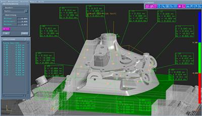
With Version 3.5 R8, Tebis also introduces a new measuring function. Measuring paths can be created with the same methods as toolpaths, using the same automation functions. A measuring probe determines the quality of the manufactured components directly at the machine. Deviations from the target are displayed at the machine controller and can be corrected without delay. Thanks to another function, a user can import, graphically display, and document the measurement result.
Another highlight of the new Tebis Version R8 is milling with 3D radius correction to compensate for tool wear. The deviation from the target can be easily calculated with the new functions for direct measuring at the machine. Tebis adds additional information to the calculated toolpaths to be evaluated by the machine controllers for radius correction. If the real tools differ from the data in the tool library, the user can enter the correction values directly into the controller.
Contact Details

Related Glossary Terms
- gang cutting ( milling)
gang cutting ( milling)
Machining with several cutters mounted on a single arbor, generally for simultaneous cutting.
- milling
milling
Machining operation in which metal or other material is removed by applying power to a rotating cutter. In vertical milling, the cutting tool is mounted vertically on the spindle. In horizontal milling, the cutting tool is mounted horizontally, either directly on the spindle or on an arbor. Horizontal milling is further broken down into conventional milling, where the cutter rotates opposite the direction of feed, or “up” into the workpiece; and climb milling, where the cutter rotates in the direction of feed, or “down” into the workpiece. Milling operations include plane or surface milling, endmilling, facemilling, angle milling, form milling and profiling.