Mori Seiki has started taking orders for the ULTRASONIC 65 monoBLOCK equipped with ultrasonic machining functions and the LASERTEC 65 Shape equipped with laser machining functions. Both machines are designed based on the DMU 65 monoBLOCK 5-axis control machining center made by Mori Seiki's collaboration partner, GILDEMEISTER AG of Germany.
The DMU 65 monoBLOCK is part of the new DMU monoBLOCK series of next generation machine tools with excellent cost performance. The DMU 65 monoBLOCK uses a 2-axis trunnion table for the first time in the DMU monoBLOCK series, handling large workpieces of up to 2200 lbs. The machine features a compact design with a footprint of 24.6 sq. ft., as well as a large door with an opening width of 56" The expansive door opening offers a wide work area and improved access to the machine. It also allows easy access for loading and unloading large workpieces by crane.
These two machines have been launched in response to customer demand for 5-axis machining of difficult-to-cut materials such as ceramic and super hard metals while maintaining fine cutting and environment-friendly machining. And there has also been growing demand for 5-axis machining center, as the workpieces become more complicated. Each of the newly released 5-axis machining centers improves productivity and cost performance by performing multiple processes that usually require special machines.
The ULTRASONIC actuator system used on the spindle is a patented technology of GILDEMEISTER, allowing a 5-axis machining center to perform ultrasonic machining through HSK interface. Ultrasonic machining reduces cutting forces by applying longitudinal ultrasonic vibration to rotational movement of a tool during grinding. For this reason, ultrasonic machining can significantly improve machining quality in regards of surface finishes of less than Ra 0.2 micrometers as well as reduction of micro-cracking of extremely hard, but brittle material including glass, ceramic and super hard metal.
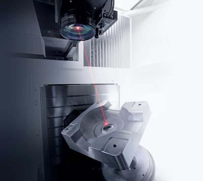
Ultrasonic machining is also a process that attracts attention from the dental prosthesis market including manufacturing of artificial teeth and implants, but the ULTRASONIC 65 monoBLOCK can also handle much larger workpieces. The machine is suitable for grinding glass ceramic lenses for artificial satellites, parts for semiconductors and aircraft engine parts made from Carbon Silicon or Nitric Silicon. The ULTRASONIC 65 monoBLOCK realizes high-efficiency machining of large-diameter workpiece of high-tech materials by integrating 5-axis milling and By mounting a fiber laser scanning head on the spindle through the HSK interface, laser surface texturing can be performed on a 5-axis machining center. Surface texturing is a machining method used to produce various patterns such as wood grain and leather grain on workpiece surfaces.
The LASERTEC 65 Shape opens up new possibilities by enabling more complex geometrically defined 3D-structures in free-forms. Laser surface texturing allows the user to create nearly unlimited wide variety of patterns (including customized 3D-textures) with greater accuracy than conventional etching in shorter machining times. It can also recreate the same pattern repeatedly. Furthermore, laser surface texturing is also an environmentally friendly machining method, especially when compared with etching, which uses chemicals and generates industrial waste.
Offering both cutting and lasering on one machine, the LASERTEC 65 Shape is capable of handling the entire machining process from roughing to laser surface finishing, and is an ideal solution for die and mold making. The LASERTEC 65 Shape provides complete machining for a wide range of dies and molds including injection molds and interior automobile components.
Additionally, the intelligent cross-process LASERSOFT-3D-TEXTURE software enables the machine to expand the range of surface texturing design variations. Monochrome image data in bitmap format printed images, as well as individually newly designed 3D-textures, can be converted into laser machining programs. The programs can be seamlessly projected onto large or free-form surfaces. The machine also features the 3D collision checking and automatic programming functions as standard, ensuring simplified operations and efficient 5-axis laser machining.
Contact Details
Related Glossary Terms
- centers
centers
Cone-shaped pins that support a workpiece by one or two ends during machining. The centers fit into holes drilled in the workpiece ends. Centers that turn with the workpiece are called “live” centers; those that do not are called “dead” centers.
- gang cutting ( milling)
gang cutting ( milling)
Machining with several cutters mounted on a single arbor, generally for simultaneous cutting.
- grinding
grinding
Machining operation in which material is removed from the workpiece by a powered abrasive wheel, stone, belt, paste, sheet, compound, slurry, etc. Takes various forms: surface grinding (creates flat and/or squared surfaces); cylindrical grinding (for external cylindrical and tapered shapes, fillets, undercuts, etc.); centerless grinding; chamfering; thread and form grinding; tool and cutter grinding; offhand grinding; lapping and polishing (grinding with extremely fine grits to create ultrasmooth surfaces); honing; and disc grinding.
- laser machining
laser machining
Intensified, pulsed beams of light generated by lasers—typically carbon dioxide or neodium-doped yttrium aluminum garnet (Nd:YAG)—that drill, weld, engrave, mark, slit and caseharden. Usually under CNC, often at both high cutting rates (100 linear in./sec.) and high power (5kW or more). Lasers also are used in conjunction with in-process quality-control monitoring systems allowing measuring accuracies of 0.00001".
- machining center
machining center
CNC machine tool capable of drilling, reaming, tapping, milling and boring. Normally comes with an automatic toolchanger. See automatic toolchanger.
- milling
milling
Machining operation in which metal or other material is removed by applying power to a rotating cutter. In vertical milling, the cutting tool is mounted vertically on the spindle. In horizontal milling, the cutting tool is mounted horizontally, either directly on the spindle or on an arbor. Horizontal milling is further broken down into conventional milling, where the cutter rotates opposite the direction of feed, or “up” into the workpiece; and climb milling, where the cutter rotates in the direction of feed, or “down” into the workpiece. Milling operations include plane or surface milling, endmilling, facemilling, angle milling, form milling and profiling.
- ultrasonic machining
ultrasonic machining
Material-removal operation in which an abrasive slurry flows between a tool, vibrating at a high frequency, and a workpiece.