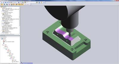
Further enhancements to the recently-introduced Waveform Roughing strategy, and Quill Support for advanced milling, are just two of the significant features in the latest release of the CAM software, Edgecam, from the Vero group.
Unveiled in the previous edition, the Waveform Roughing Strategy offers even greater stability, more precise machining and faster metal removal. The new Edgecam 2012 R2 takes this advanced process to the next level, including improvements to the entry methods, ordering and calculation speeds.
General Manager Raf Lobato says: "The Waveform Roughing Strategy gives improved tool life, constant engagement with material and constant chip load, superior material removal rates, and an improved surface finish which potentially eliminates secondary cutting cycles."
The new Advanced 5 Axis Simultaneous Milling license introduces new parameters to control the toolpath, a new dialog with images to help explain the options available and the option to machine multi-blade components.
Quills (secondary Z axis) can now be included in milling machine configurations, enabling the user to switch between the z axes, control which one is in use, and see the quills movement in Simulator.
Lobato says: "Edgecam 2012 R2 includes further improvements to the User Interface making Edgecam even more intuitive and easier to use."
When editing an Edgecam cycle the original geometry picks are now retained and do not need to be reselected unless the user chooses to. A similar time saving feature is the improved picking of edges on solid models and 2D profiles, ensuring that the user has full control of picking entities that will be used by other functions within Edgecam.
And to make it easier to manage a large set of machining instructions, it is now possible to group a number of instructions into user defined sets within the sequence browser.
External rotary slot and pocket features along a cylinder solid model can now be identified for subsequent machining. The feature attributes help the user to select the correct tool and machine the feature in rotary mode.
Steadies can now be included in Turning and Mill/Turn machine configurations, and included in the simulation of the machining sequence in Simulator.
Contact Details
Related Glossary Terms
- computer-aided manufacturing ( CAM)
computer-aided manufacturing ( CAM)
Use of computers to control machining and manufacturing processes.
- gang cutting ( milling)
gang cutting ( milling)
Machining with several cutters mounted on a single arbor, generally for simultaneous cutting.
- milling
milling
Machining operation in which metal or other material is removed by applying power to a rotating cutter. In vertical milling, the cutting tool is mounted vertically on the spindle. In horizontal milling, the cutting tool is mounted horizontally, either directly on the spindle or on an arbor. Horizontal milling is further broken down into conventional milling, where the cutter rotates opposite the direction of feed, or “up” into the workpiece; and climb milling, where the cutter rotates in the direction of feed, or “down” into the workpiece. Milling operations include plane or surface milling, endmilling, facemilling, angle milling, form milling and profiling.
- milling machine ( mill)
milling machine ( mill)
Runs endmills and arbor-mounted milling cutters. Features include a head with a spindle that drives the cutters; a column, knee and table that provide motion in the three Cartesian axes; and a base that supports the components and houses the cutting-fluid pump and reservoir. The work is mounted on the table and fed into the rotating cutter or endmill to accomplish the milling steps; vertical milling machines also feed endmills into the work by means of a spindle-mounted quill. Models range from small manual machines to big bed-type and duplex mills. All take one of three basic forms: vertical, horizontal or convertible horizontal/vertical. Vertical machines may be knee-type (the table is mounted on a knee that can be elevated) or bed-type (the table is securely supported and only moves horizontally). In general, horizontal machines are bigger and more powerful, while vertical machines are lighter but more versatile and easier to set up and operate.
- solid model
solid model
3-D model created using “building blocks.” This is the most accurate way of representing real-world objects in CAD.
- toolpath( cutter path)
toolpath( cutter path)
2-D or 3-D path generated by program code or a CAM system and followed by tool when machining a part.
- turning
turning
Workpiece is held in a chuck, mounted on a face plate or secured between centers and rotated while a cutting tool, normally a single-point tool, is fed into it along its periphery or across its end or face. Takes the form of straight turning (cutting along the periphery of the workpiece); taper turning (creating a taper); step turning (turning different-size diameters on the same work); chamfering (beveling an edge or shoulder); facing (cutting on an end); turning threads (usually external but can be internal); roughing (high-volume metal removal); and finishing (final light cuts). Performed on lathes, turning centers, chucking machines, automatic screw machines and similar machines.
