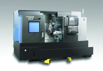
Doosan Machine Tools has added the PUMA 2600 SY II to its lineup of high-productivity turning centers. The PUMA 2600 SY II is a high-performance, 10-inch class, subspindle Y-axis horizontal turning center designed to craft high precision parts from a range of difficult-to-machine materials.
The PUMA 2600 SY II has a newly designed bed for unprecedented rigidity and accuracy. A standard active thermal compensation system decreases the effects thermal deformation by 60 to 70 percent compared to the previous model. NTN sliding bearings have been applied to all axis box guide ways on the carriage, improving fine movement by more than 40 percent and wear resistance by more than 30 percent. The feed box and X-axis bearing mount have been reinforced for high rigidity.
The built in spindle minimizes vibration and provides better acceleration and a smooth, fast ramp-up. It generates a maximum 22 kW (30 hp.) and 599Nm (442.1 ft-lbs) of torque. Improved spindle run out (6 μm) has been achieved by changing the structure of the spindle bearings and making it more suitable to high precision and improved surface finishes.
The 12-station milling turret has also been redesigned for improved durability and increased clamping force. BMT tooling provides unsurpassed rigidity for heavy chip removal, fine surface finishes, long boring bar overhang ratios, and extended tool life.
The Doosan FANUC i series operation panel has a new ergonomic design and an updated Easy Operation Package (EOP) with improved setup, operation and maintenance programing.
“The new PUMA 2600 SY II is the end result of a scientific study to improve on every aspect of the previous model,” states Jim Shiner, director of sales and marketing at Doosan Machine Tools America. “This objective approach allowed us to work with feedback from our customers and craft a turning center that meets their needs for speed, strength and accuracy.”
Contact Details
Related Glossary Terms
- boring
boring
Enlarging a hole that already has been drilled or cored. Generally, it is an operation of truing the previously drilled hole with a single-point, lathe-type tool. Boring is essentially internal turning, in that usually a single-point cutting tool forms the internal shape. Some tools are available with two cutting edges to balance cutting forces.
- boring bar
boring bar
Essentially a cantilever beam that holds one or more cutting tools in position during a boring operation. Can be held stationary and moved axially while the workpiece revolves around it, or revolved and moved axially while the workpiece is held stationary, or a combination of these actions. Installed on milling, drilling and boring machines, as well as lathes and machining centers.
- centers
centers
Cone-shaped pins that support a workpiece by one or two ends during machining. The centers fit into holes drilled in the workpiece ends. Centers that turn with the workpiece are called “live” centers; those that do not are called “dead” centers.
- feed
feed
Rate of change of position of the tool as a whole, relative to the workpiece while cutting.
- gang cutting ( milling)
gang cutting ( milling)
Machining with several cutters mounted on a single arbor, generally for simultaneous cutting.
- milling
milling
Machining operation in which metal or other material is removed by applying power to a rotating cutter. In vertical milling, the cutting tool is mounted vertically on the spindle. In horizontal milling, the cutting tool is mounted horizontally, either directly on the spindle or on an arbor. Horizontal milling is further broken down into conventional milling, where the cutter rotates opposite the direction of feed, or “up” into the workpiece; and climb milling, where the cutter rotates in the direction of feed, or “down” into the workpiece. Milling operations include plane or surface milling, endmilling, facemilling, angle milling, form milling and profiling.
- turning
turning
Workpiece is held in a chuck, mounted on a face plate or secured between centers and rotated while a cutting tool, normally a single-point tool, is fed into it along its periphery or across its end or face. Takes the form of straight turning (cutting along the periphery of the workpiece); taper turning (creating a taper); step turning (turning different-size diameters on the same work); chamfering (beveling an edge or shoulder); facing (cutting on an end); turning threads (usually external but can be internal); roughing (high-volume metal removal); and finishing (final light cuts). Performed on lathes, turning centers, chucking machines, automatic screw machines and similar machines.
- wear resistance
wear resistance
Ability of the tool to withstand stresses that cause it to wear during cutting; an attribute linked to alloy composition, base material, thermal conditions, type of tooling and operation and other variables.
