Production Module Upgrade

September 01, 2011

Third Wave Systems introduced its newest machining modeling capabilities: part distortion and tool deflection. The product has been under development for more than five years, and will be sold as an upgrade to the company's NC program optimization software, Production Module, beginning in November of 2011.

Its most well-known product, AdvantEdge FEM, is finite element analysis software developed specifically to model material behavior during metal cutting processes such as drilling, milling, grooving, and turning. The same material models used for this finite element analysis are also incorporated into Production Module, Third Wave's CAE software that provides a more comprehensive, transformative solution for toolpath analysis and optimization.

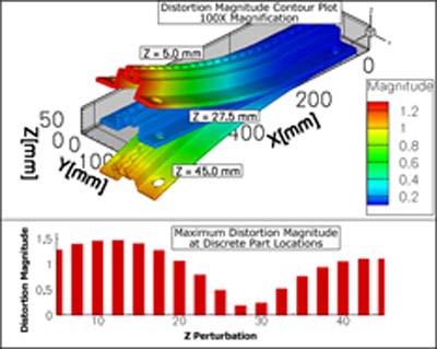
With the release of its predictive part distortion and tool deflection capabilities, Third Wave Production Module users will be able to analyze legacy and new machining strategies with consideration not only for tool performance and production times, but also for the dimensional accuracy of final parts. With the ability to simulate, analyze, and visualize multiple part geometries and their impact on distortion, Production Module may also be used earlier in the product design cycle by engineers looking to design products for future manufacturability.

Indeed, the new upgrade to Production Module will offer a drastic departure from the current practices for limiting part distortion. Instead of making machining improvements based on countless trial-and-error tests, or sending parts out for secondary operations after machining, both of which can be costly and time-consuming, manufacturers will be empowered to proactively identify machining parameters that deliver optimal part quality in minutes, with only a few clicks of a mouse. The technology presents an immediate business case for companies looking to innovate with minimal risk to their bottom lines.

Consistent with its current software packages, Third Wave Systems engineers have developed this new modeling upgrade with usability in mind. The software reads 5-axis APT and G-codes, permits importing of STEP and STL files, incorporates a database of workpiece bulk stresses, and automatically generates a thin-wall mesh. Factors such as cutting force distribution along the flute length, instantaneous cutting forces, and changes in cross-sectional moments of inertia along a tapered tool are also modeled automatically, further simplifying process setup.

Related Glossary Terms

  • computer-aided engineering ( CAE)

    computer-aided engineering ( CAE)

    Engineering functions performed with the help of computers and special software. Includes functions such as determining a material’s ability to withstand stresses.

  • cutting force

    cutting force

    Engagement of a tool’s cutting edge with a workpiece generates a cutting force. Such a cutting force combines tangential, feed and radial forces, which can be measured by a dynamometer. Of the three cutting force components, tangential force is the greatest. Tangential force generates torque and accounts for more than 95 percent of the machining power. See dynamometer.

  • gang cutting ( milling)

    gang cutting ( milling)

    Machining with several cutters mounted on a single arbor, generally for simultaneous cutting.

  • grooving

    grooving

    Machining grooves and shallow channels. Example: grooving ball-bearing raceways. Typically performed by tools that are capable of light cuts at high feed rates. Imparts high-quality finish.

  • milling

    milling

    Machining operation in which metal or other material is removed by applying power to a rotating cutter. In vertical milling, the cutting tool is mounted vertically on the spindle. In horizontal milling, the cutting tool is mounted horizontally, either directly on the spindle or on an arbor. Horizontal milling is further broken down into conventional milling, where the cutter rotates opposite the direction of feed, or “up” into the workpiece; and climb milling, where the cutter rotates in the direction of feed, or “down” into the workpiece. Milling operations include plane or surface milling, endmilling, facemilling, angle milling, form milling and profiling.

  • numerical control ( NC)

    numerical control ( NC)

    Any controlled equipment that allows an operator to program its movement by entering a series of coded numbers and symbols. See CNC, computer numerical control; DNC, direct numerical control.

  • toolpath( cutter path)

    toolpath( cutter path)

    2-D or 3-D path generated by program code or a CAM system and followed by tool when machining a part.

  • turning

    turning

    Workpiece is held in a chuck, mounted on a face plate or secured between centers and rotated while a cutting tool, normally a single-point tool, is fed into it along its periphery or across its end or face. Takes the form of straight turning (cutting along the periphery of the workpiece); taper turning (creating a taper); step turning (turning different-size diameters on the same work); chamfering (beveling an edge or shoulder); facing (cutting on an end); turning threads (usually external but can be internal); roughing (high-volume metal removal); and finishing (final light cuts). Performed on lathes, turning centers, chucking machines, automatic screw machines and similar machines.