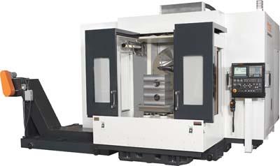
Mazak Corp.'s ORBITEC 20 employs a unique headstock design to generate turned features on large valves and other big, odd-shaped parts with ease and accuracy. This large-part machining center also integrates with other Mazak products to form a Multi-Tasking solution with productivity advantages.
For example, the ORBITEC 20 can be integrated with the heavy-duty INTEGREX i-630V 5-axis machine and pre-engineered PALLETECH Manufacturing System to achieve a fully automated manufacturing cell that can provide the flexibility required for shorter product life cycles, reduce in-process inventory and allow for just-in-time production.
Equipped with a standard two-pallet changer, along with the availability of Mazak's PMC-WEB cell controller software, the ORBITEC 20 easily pairs with the PALLETECH. Because both the ORBITEC and INTEGREX machines utilize a common pallet size, parts can undergo various turning operations on the ORBITEC 20 and then transfer over to the INTEGREX via the PALLETECH for final processing without having to be re-fixtured. With the PMC-WEB cell controller software over standard PCs and networks, shop management can monitor operations, view and change schedules on-the-fly, manage part program files from anywhere on the network, track tool life/breakage and issue instructions to the shop floor. Users are able to interrupt a planned machining queue and produce an emergency part with no cost penalty.
The ORBITEC 20's patented headstock effectively generates turned features on parts by keeping the workpieces clamped and stationary, moving only the cutting tool. As an internally counter balanced system, the ORBITEC 20's headstock, with 40 hp (30 kW), 600-rpm integrated spindle motor, keeps tool tips facing either toward or away from the centerline of rotation while tools orbit around workpieces. This provides stable precision machining and less part interference because tools do not protrude beyond the rotating headstock when working on larger diameters.
The headstock design is a circle, as opposed to linear slides, within a circle for accurate linearly interpolated X-axis tool movement. For increased part accessibility, the machine's X-axis stroke measures 11.02", (280mm), while its U, V, and Z-axis strokes are 23.62" (600mm), 23.62" (600mm), and 48.43" (1,230mm) respectively. The machine turns diameters up to 20" (508mm), depending on the tools being used, on parts fitting into a working area of 41.34" (1,050mm) in diameter and 51.18" (1,300mm) in height.
Part processing versatility is increased with the ORBITEC 20's wide range of machining operations, including generating phonographic finishes on flange surfaces, cutting tapered bores, and grooving in feed-out operations. The machine also does trepanning, threading, internal grooving, drilling and concave machining.
Contact Details
Related Glossary Terms
- grooving
grooving
Machining grooves and shallow channels. Example: grooving ball-bearing raceways. Typically performed by tools that are capable of light cuts at high feed rates. Imparts high-quality finish.
- just-in-time ( JIT)
just-in-time ( JIT)
Philosophy based on identifying, then removing, impediments to productivity. Applies to machining processes, inventory control, rejects, changeover time and other elements affecting production.
- machining center
machining center
CNC machine tool capable of drilling, reaming, tapping, milling and boring. Normally comes with an automatic toolchanger. See automatic toolchanger.
- precision machining ( precision measurement)
precision machining ( precision measurement)
Machining and measuring to exacting standards. Four basic considerations are: dimensions, or geometrical characteristics such as lengths, angles and diameters of which the sizes are numerically specified; limits, or the maximum and minimum sizes permissible for a specified dimension; tolerances, or the total permissible variations in size; and allowances, or the prescribed differences in dimensions between mating parts.
- threading
threading
Process of both external (e.g., thread milling) and internal (e.g., tapping, thread milling) cutting, turning and rolling of threads into particular material. Standardized specifications are available to determine the desired results of the threading process. Numerous thread-series designations are written for specific applications. Threading often is performed on a lathe. Specifications such as thread height are critical in determining the strength of the threads. The material used is taken into consideration in determining the expected results of any particular application for that threaded piece. In external threading, a calculated depth is required as well as a particular angle to the cut. To perform internal threading, the exact diameter to bore the hole is critical before threading. The threads are distinguished from one another by the amount of tolerance and/or allowance that is specified. See turning.
- trepanning
trepanning
Drilling deep holes that are too large to be drilled by high-pressure coolant drills or gundrills. Trepanning generates a solid core and normally requires a big, powerful machine. Shallow trepanning operations can be performed on modified engine or turret lathes or on boring machines. See boring; drilling; spade drilling.
- turning
turning
Workpiece is held in a chuck, mounted on a face plate or secured between centers and rotated while a cutting tool, normally a single-point tool, is fed into it along its periphery or across its end or face. Takes the form of straight turning (cutting along the periphery of the workpiece); taper turning (creating a taper); step turning (turning different-size diameters on the same work); chamfering (beveling an edge or shoulder); facing (cutting on an end); turning threads (usually external but can be internal); roughing (high-volume metal removal); and finishing (final light cuts). Performed on lathes, turning centers, chucking machines, automatic screw machines and similar machines.