Mastercam X9 for SOLIDWORKS

March 29, 2016

Mastercam X9 for SOLIDWORKS is a CAM application that is fully integrated into Dassault Systèmes’ SOLIDWORKS. The latest release features Dynamic Motion technology improvements, 3D milling enhancements and multiaxis improvements. And, Mastercam for SOLIDWORKS Lathe, Mill or Multiaxis is included with the purchase of the comparable standalone Mastercam X9 product.

Dynamic Motion toolpaths follow a proprietary and sophisticated set of rules that take into consideration a broad data set. To create the most efficient cutting motion possible, Dynamic toolpaths calculate not only the area where material will be removed; they also take into account the changing condition of the material throughout various stages of machining. With Mastercam for SOLIDWORKS X9, 2D HST Dynamic Mill, Peel Mill and 3D Dynamic OptiRough support a conventional feed rate when set to a Zigzag cutting method.

3D HST roughing has been consolidated from six toolpaths down to two toolpaths: Dynamic OptiRough and Area Roughing. The efficiency of rest roughing linking heights for 3D HST toolpaths has been greatly improved. 3D HST waterline toolpaths now include an option to machine your part from bottom to top.  And, hybrid flat area processing is now available. You can choose to include the flat areas of your part in the toolpath, ignore the flat areas, or only machine the flats.

Now available for Port Expert, minimize tilting creates the most efficient toolpath possible through a port, according to the company. Multiaxis toolpaths are displayed as normal tool motion instead of vectors in the graphics window. All advanced multiaxis toolpaths, such as Port Expert and Blade Expert, are now processed through the Multi-Threading Manager, leaving users free to work while processing. And, the new Multiaxis Link toolpath allows users to link multiple toolpaths together to create a safe linking move between them.

Also available in Mastercam X9 for SOLIDWORKS:

Option to project the selected items to the Toolplane has been added to the Chain Manager for 2D Toolpaths and for 3D Toolpath Containments. When SOLIDWORKS Solid Bodies, Faces, Features or Surfaces are selected, a silhouette of the selected items will automatically be generated.

Multiple Mastercam Simulator improvements, such as the new Adaptive Quality tool and motion controller support.

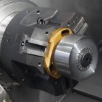
Lathe C-axis operations, as well as Lathe Misc Op operations, are now available.

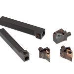
Ability to insert, delete or otherwise rearrange holder segments using the right-mouse context menu.

Barrel tool support, as well as thread mill support, has been added.

Related Glossary Terms

  • computer-aided manufacturing ( CAM)

    computer-aided manufacturing ( CAM)

    Use of computers to control machining and manufacturing processes.

  • feed

    feed

    Rate of change of position of the tool as a whole, relative to the workpiece while cutting.

  • flat ( screw flat)

    flat ( screw flat)

    Flat surface machined into the shank of a cutting tool for enhanced holding of the tool.

  • gang cutting ( milling)

    gang cutting ( milling)

    Machining with several cutters mounted on a single arbor, generally for simultaneous cutting.

  • lathe

    lathe

    Turning machine capable of sawing, milling, grinding, gear-cutting, drilling, reaming, boring, threading, facing, chamfering, grooving, knurling, spinning, parting, necking, taper-cutting, and cam- and eccentric-cutting, as well as step- and straight-turning. Comes in a variety of forms, ranging from manual to semiautomatic to fully automatic, with major types being engine lathes, turning and contouring lathes, turret lathes and numerical-control lathes. The engine lathe consists of a headstock and spindle, tailstock, bed, carriage (complete with apron) and cross slides. Features include gear- (speed) and feed-selector levers, toolpost, compound rest, lead screw and reversing lead screw, threading dial and rapid-traverse lever. Special lathe types include through-the-spindle, camshaft and crankshaft, brake drum and rotor, spinning and gun-barrel machines. Toolroom and bench lathes are used for precision work; the former for tool-and-die work and similar tasks, the latter for small workpieces (instruments, watches), normally without a power feed. Models are typically designated according to their “swing,” or the largest-diameter workpiece that can be rotated; bed length, or the distance between centers; and horsepower generated. See turning machine.

  • milling

    milling

    Machining operation in which metal or other material is removed by applying power to a rotating cutter. In vertical milling, the cutting tool is mounted vertically on the spindle. In horizontal milling, the cutting tool is mounted horizontally, either directly on the spindle or on an arbor. Horizontal milling is further broken down into conventional milling, where the cutter rotates opposite the direction of feed, or “up” into the workpiece; and climb milling, where the cutter rotates in the direction of feed, or “down” into the workpiece. Milling operations include plane or surface milling, endmilling, facemilling, angle milling, form milling and profiling.

  • milling machine ( mill)

    milling machine ( mill)

    Runs endmills and arbor-mounted milling cutters. Features include a head with a spindle that drives the cutters; a column, knee and table that provide motion in the three Cartesian axes; and a base that supports the components and houses the cutting-fluid pump and reservoir. The work is mounted on the table and fed into the rotating cutter or endmill to accomplish the milling steps; vertical milling machines also feed endmills into the work by means of a spindle-mounted quill. Models range from small manual machines to big bed-type and duplex mills. All take one of three basic forms: vertical, horizontal or convertible horizontal/vertical. Vertical machines may be knee-type (the table is mounted on a knee that can be elevated) or bed-type (the table is securely supported and only moves horizontally). In general, horizontal machines are bigger and more powerful, while vertical machines are lighter but more versatile and easier to set up and operate.

  • toolpath( cutter path)

    toolpath( cutter path)

    2-D or 3-D path generated by program code or a CAM system and followed by tool when machining a part.