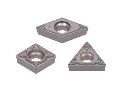
Tungaloy enhances its ISO positive turning inserts in “-01” geometry to include a 0.4 mm (0.0157") nose radius prepared in a minus tolerance specifically for precision finishing in Swiss turning applications. The new -01 geometry is designed to deliver consistent chip control at extremely light cutting depths of 0.5 mm (0.020") or smaller.
The introduction of a 0.4 mm nose radius insert is implemented due to the increased demands in the Swiss-style turning market where workpieces with 0.4 mm corner radius requirements are as popular as workpieces with 0.2 mm radii. In addition, these corner radii are often required to be finished equal to or smaller than the required radius dimensions in order to minimize the impact on dimensional accuracy. Therefore, the insert nose radii of the -01 geometry are all designed and constructed in a minus tolerance to the nominal nose radii, and not exceeding it.
Combined with the existing -JS geometry, the first-choice for small part turning, the enhanced lineup of the -01 geometry provides customers with optimal chipbreaker options for various cutting depths and feed rates in Swiss turning operations.
The -01 geometry is optimized for cutting depths of 0.5 mm (0.020") or less, while -JS geometries are effective for depths of cut ranging from 0.5 mm to 3.0 mm (0.020" to 0.118").
At a Glance
-01 geometry provides good chip control in DOC ≤0.5 mm
Ideal for turning into shoulders with strict corner radius requirements
Sharp cutting edge provides chatter stability and superior surface integrity in machining small-diameter bar stock
With -01 and -JS geometries combined, extremely light cutting depths of ≤0.5 mm all the way up to 3.0 mm are now covered
10 inserts to be added in this expansion
Contact Details
Related Glossary Terms
- chatter
chatter
Condition of vibration involving the machine, workpiece and cutting tool. Once this condition arises, it is often self-sustaining until the problem is corrected. Chatter can be identified when lines or grooves appear at regular intervals in the workpiece. These lines or grooves are caused by the teeth of the cutter as they vibrate in and out of the workpiece and their spacing depends on the frequency of vibration.
- chipbreaker
chipbreaker
Groove or other tool geometry that breaks chips into small fragments as they come off the workpiece. Designed to prevent chips from becoming so long that they are difficult to control, catch in turning parts and cause safety problems.
- feed
feed
Rate of change of position of the tool as a whole, relative to the workpiece while cutting.
- tolerance
tolerance
Minimum and maximum amount a workpiece dimension is allowed to vary from a set standard and still be acceptable.
- turning
turning
Workpiece is held in a chuck, mounted on a face plate or secured between centers and rotated while a cutting tool, normally a single-point tool, is fed into it along its periphery or across its end or face. Takes the form of straight turning (cutting along the periphery of the workpiece); taper turning (creating a taper); step turning (turning different-size diameters on the same work); chamfering (beveling an edge or shoulder); facing (cutting on an end); turning threads (usually external but can be internal); roughing (high-volume metal removal); and finishing (final light cuts). Performed on lathes, turning centers, chucking machines, automatic screw machines and similar machines.

