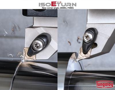
Tungaloy has expanded its economical ISO-EcoTurn turning insert and toolholders system by adding GNMG insert with a 70 degree nose angle and FNMG insert with a 45 degree nose angle.
With conventional CNMG or DNMG turning inserts, chip jamming and re-cutting can be a common challenge during profile turning or face turning processes when the cutting is performed in the direction away from the work center in one continuous path.
ISO-EcoTurn’s new GNMG and FNMG inserts each features a reduced nose angle of 70 degrees and 45 degrees, compared with traditional CNMG and DNMG inserts. The increased clearance on the cutting edge allows better chip flow and reduced chip re-cutting issues when face turning the wall. Reduced nose angle also contributes to lower cutting force, minimizing unpredictable tool failure and chatter during machining.
The new inserts include two chipbreaker styles: TM for general purpose applications and TSF for finish turning. The inserts are offered in the new generation of CVD grades for steel turning: T9215 and T9225, along with AH8015, a PVD grade for high temperature alloys.
The new GNMG and FNMG inserts can be mounted on a standard turning toolholder for CNMG or DNMG inserts. Even though the new inserts feature reduced nose angles on both ends, the central part of the insert body has the identical size and shape as CNMG or DNMG. This eliminates the need to invest in new toolholders.
Total of 39 inserts have been added in this expansion.
Contact Details
Related Glossary Terms
- alloys
alloys
Substances having metallic properties and being composed of two or more chemical elements of which at least one is a metal.
- chatter
chatter
Condition of vibration involving the machine, workpiece and cutting tool. Once this condition arises, it is often self-sustaining until the problem is corrected. Chatter can be identified when lines or grooves appear at regular intervals in the workpiece. These lines or grooves are caused by the teeth of the cutter as they vibrate in and out of the workpiece and their spacing depends on the frequency of vibration.
- chemical vapor deposition ( CVD)
chemical vapor deposition ( CVD)
High-temperature (1,000° C or higher), atmosphere-controlled process in which a chemical reaction is induced for the purpose of depositing a coating 2µm to 12µm thick on a tool’s surface. See coated tools; PVD, physical vapor deposition.
- chipbreaker
chipbreaker
Groove or other tool geometry that breaks chips into small fragments as they come off the workpiece. Designed to prevent chips from becoming so long that they are difficult to control, catch in turning parts and cause safety problems.
- clearance
clearance
Space provided behind a tool’s land or relief to prevent rubbing and subsequent premature deterioration of the tool. See land; relief.
- cutting force
cutting force
Engagement of a tool’s cutting edge with a workpiece generates a cutting force. Such a cutting force combines tangential, feed and radial forces, which can be measured by a dynamometer. Of the three cutting force components, tangential force is the greatest. Tangential force generates torque and accounts for more than 95 percent of the machining power. See dynamometer.
- physical vapor deposition ( PVD)
physical vapor deposition ( PVD)
Tool-coating process performed at low temperature (500° C), compared to chemical vapor deposition (1,000° C). Employs electric field to generate necessary heat for depositing coating on a tool’s surface. See CVD, chemical vapor deposition.
- toolholder
toolholder
Secures a cutting tool during a machining operation. Basic types include block, cartridge, chuck, collet, fixed, modular, quick-change and rotating.
- turning
turning
Workpiece is held in a chuck, mounted on a face plate or secured between centers and rotated while a cutting tool, normally a single-point tool, is fed into it along its periphery or across its end or face. Takes the form of straight turning (cutting along the periphery of the workpiece); taper turning (creating a taper); step turning (turning different-size diameters on the same work); chamfering (beveling an edge or shoulder); facing (cutting on an end); turning threads (usually external but can be internal); roughing (high-volume metal removal); and finishing (final light cuts). Performed on lathes, turning centers, chucking machines, automatic screw machines and similar machines.

