OPEN MIND Technologies AG has released the latest version of its CAM system, hyperMILL 2017.1. Users now benefit from many new functions and optimization tools that make programming faster while reducing auxiliary processing times when carrying out machining jobs. The software developer has also made crucial additions to hyperCAD-S, its proprietary CAD for CAM solution.
Manufacturing companies heavily rely on multifunctional mill/turning centers to optimize their machining processes. OPEN MIND supports this trend and has added many new mill/turning functions to hyperMILL 2017.1.
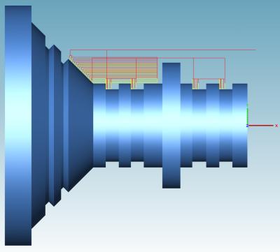
The extended chip break function for turning operations allows the customer to machine hard and soft materials with more flexibility than ever before. New functions make it possible to remove chips safely for non-falling contours. The machining length can be defined in combination with a short stop to break swarf. This ensures the workpiece is not damaged by swarf getting wrapped around the spindle. It’s also possible to maintain high surface quality with the machining length defined in combination with a short pause. The user can select from two methods to specify the stop, define the dwell time or even the number of spindle rotations. Greater control of the chip break is possible where the area to be machined is divided into multiple sections that are then machined in a specified order.
The new release offers a number of new functions and expansions for 2.5D and 3D machining. hyperMILL 2017.1 supports cutter radius compensation when using 2D thread milling and 2D helical drilling strategies. If the tool radius changes, hyperMILL automatically adjusts the programmed path. The user has two options for how this adjustment is made: the compensated path option or the compensated centre path option.
The new 3D cutting edge machining strategy is one of the highlights for 3D milling jobs. This strategy enables efficient machining, particularly for cutting blades, which are frequently used in tool engineering. Roughing and finishing operations can easily be generated via a 3D curve selection. The rest material machining is generated via the "reference job" option. Here, the rest material areas of the previous machining operation are also included in each case. Toolpath smoothing ensures a better milling result if the contours are of poor quality.
The new version also expands the scope of the hyperMILL MAXX Machining performance package. hyperMILL 2017.1 allows the spindle speed to be adjusted in the plunge macro for roughing. Modifying the spindle speed and specifying a dwell time for the speed change ensure more tool-friendly machining. This option also increases process reliability.
Users can benefit from two new functions for 5-axis swarf cutting with a curve. The perfect surface and equally perfect curve are created automatically forswarf cutting based on a simple face selection. This feature automatically fillets interior corners, so the programmer can eliminate the input of additional geometries when pocket and fillet machining.
Three basic improvements make the newest version of the hyperCAD-S CAD solution stand out. This is the draft, curvature and selection function analyses. The new selection functions make selecting CAD elements particularly convenient. The new draft and curvature analyses help users quickly view and examine milling areas or radii sizes.
Contact Details
Related Glossary Terms
- centers
centers
Cone-shaped pins that support a workpiece by one or two ends during machining. The centers fit into holes drilled in the workpiece ends. Centers that turn with the workpiece are called “live” centers; those that do not are called “dead” centers.
- computer-aided design ( CAD)
computer-aided design ( CAD)
Product-design functions performed with the help of computers and special software.
- computer-aided manufacturing ( CAM)
computer-aided manufacturing ( CAM)
Use of computers to control machining and manufacturing processes.
- fillet
fillet
Rounded corner or arc that blends together two intersecting curves or lines. In three dimensions, a fillet surface is a transition surface that blends together two surfaces.
- gang cutting ( milling)
gang cutting ( milling)
Machining with several cutters mounted on a single arbor, generally for simultaneous cutting.
- milling
milling
Machining operation in which metal or other material is removed by applying power to a rotating cutter. In vertical milling, the cutting tool is mounted vertically on the spindle. In horizontal milling, the cutting tool is mounted horizontally, either directly on the spindle or on an arbor. Horizontal milling is further broken down into conventional milling, where the cutter rotates opposite the direction of feed, or “up” into the workpiece; and climb milling, where the cutter rotates in the direction of feed, or “down” into the workpiece. Milling operations include plane or surface milling, endmilling, facemilling, angle milling, form milling and profiling.
- swarf
swarf
Metal fines and grinding wheel particles generated during grinding.
- toolpath( cutter path)
toolpath( cutter path)
2-D or 3-D path generated by program code or a CAM system and followed by tool when machining a part.
- turning
turning
Workpiece is held in a chuck, mounted on a face plate or secured between centers and rotated while a cutting tool, normally a single-point tool, is fed into it along its periphery or across its end or face. Takes the form of straight turning (cutting along the periphery of the workpiece); taper turning (creating a taper); step turning (turning different-size diameters on the same work); chamfering (beveling an edge or shoulder); facing (cutting on an end); turning threads (usually external but can be internal); roughing (high-volume metal removal); and finishing (final light cuts). Performed on lathes, turning centers, chucking machines, automatic screw machines and similar machines.