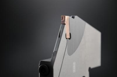
HORN is introducing the EH geometry, a new development based on the S100 grooving system, for parting-off at high feed rates. The stable cutting edge enables feed rates in the range of f = 0.25-0.4 mm/rev, during grooving and parting-off, which results in reduced machining time across multiple operations. Reliable chip evacuation and control is ensured by a special chip formation. High feed rates require a stable machine when grooving and parting-off, as well as secure clamping of the workpiece. Starting from a feed rate of 0.3 mm/rev (0.012”/rev), HORN recommends reducing the infeed for the first 3—4 mm (0.118”- 0.157”) during grooving and parting-off. Due to their stability, holders and cassettes are often the first choice when grooving along the Y-axis. HORN offers the single-edged grooving inserts in widths of 3 mm (0.118”) and 4 mm (0.157”).
In 2019, HORN expanded the S100 grooving system by adding new holder variants for grooving on turn-mill centers with the feed along the Y-axis.
The process enables high-performance parting-off with high cutting values resulting in a shorter machining time. These holder variants offer the ability to part-off large diameters using a compact holder as well as parting-off with narrower widths.
Substantial cutting forces are generated while parting-off large diameter workpieces. The available space inside machines often does not allow the use of large cross-section tools. The tool holder’s new insert arrangement allows the cutting forces to be absorbed by the main cross-section of the part-off tool. This results in higher rigidity of the overall system for a given cross section, allowing higher feed rates for the width of insert. The transmission of force along the longitudinal direction of the tool allows narrower holders to be used to achieve the same system rigidity.
Contact Details
Related Glossary Terms
- centers
centers
Cone-shaped pins that support a workpiece by one or two ends during machining. The centers fit into holes drilled in the workpiece ends. Centers that turn with the workpiece are called “live” centers; those that do not are called “dead” centers.
- feed
feed
Rate of change of position of the tool as a whole, relative to the workpiece while cutting.
- grooving
grooving
Machining grooves and shallow channels. Example: grooving ball-bearing raceways. Typically performed by tools that are capable of light cuts at high feed rates. Imparts high-quality finish.

