The latest release of Edgecam's manufacturing software from Vero USA contains a number of important new and enhanced items of CAD and CAM functionality for milling, turning and wire EDMing.
Highlights include an upgrade to the multispindle lathe setup, a new port machining module for its renowned 5-axis cycle and significant time savings through the enhanced hole cycle.
Overall, Edgecam 2015 R2 has around 50 items of new and enhanced functionality. The Lathe Set-Up command has been enhanced, allowing for clearer definition of Main and Sub-Spindle components. This leads to a better understanding of which machining features are active, and means multiple transfers can be made between spindles.
And the new Spindle Set-Up command makes it easier to edit the sequence window. Also, the subspindle part can be machined away from its home position.
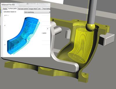
The Advanced 5-Axis Cycle capability has a new Port Machining module, offering both roughing and finishing strategies. The toolpath reaches the full area with a single path, offering two types of cut pattern.
Using the enhanced Hole Cycle in Edgecam 2015 R2 gives significant time savings. Where voids or intersecting holes are detected, the toolpath is automatically adjusted, increasing the feedrate while the tool is not cutting. The NC output is adjusted using the high feedrate of the machine tool.
Numerous enhancements have been made to Edgecam's internal modelling software, Edgecam Workflow Solids. For the rapid creation of uniform profiles, EWS has introduced a Slotting Tool command, which quickly and easily adopts any profile shape, adding width and depth to the feature. Fillets and corner blends are also supported.
Edgecam 2015 R2 introduces the ability to automatically add dimensional constraints in EWS, through the Sketch Analysis command. Users save a significant amount of time when creating sketches extracted from DXF/DWG files.
Wire EDM benefits from further Advanced controls for Edgecam's 2- and 4-axis wire EDM machining cycles. Not only has Corner Relief been added, but the system now offers four variants of the command. For example, where a razor sharp edge is required on external corners, the Loop control is selected ... while choosing Circle creates relief on an internal corner.
Since its initial release the Edgecam Wire EDM cycle has supported interruptions to the wire path in order to introduce Glue Stops, or tags. This command has been enhanced in 2015 R2, automatically producing multiple tags for large, heavy or complex parts.
The latest release delivers additional collision avoidance by checking Link moves between all milling cycles. Link moves are now automatically checked against Stock and Fixtures, with the tool retracting to a safe height where collisions are detected.
In addition, the items of new and enhanced functionality include support for M&H probing, simulation of screw threads, new machine tool configuration for turning on milling machines, CAD links for Creo Parametric files, and support for lathes with subspindles offset from centerline.
Edgecam 2015 R2 supports touch probes from M&H. Users can measure workpieces and simulate the probe movements with six individual probing cycles. Each cycle has also been enhanced with eight new functions, giving a wider choice of inspection data.
Machine simulation of thread cutting has been introduced into the new release, allowing users to view and analyse thread forms created by the Thread Turn cycle. It gives a choice of viewing an accurate representation of the thread, or a pictorial image.
Enhanced machine tool configuration ensures manufacturers can avoid potential collisions while machining on lathes with main and subspindles – the subspindle locations can be repositioned using the new ‘Offset X location' function. And with the increasing popularity in mill-turn machines, further evolution in Machine Tool configurations means users can now create ‘table-table,' ‘head-table' and ‘nutated table-table' machines, including TNC control.
Finally, thanks to new support for Creo Parametric files, users can now launch Edgecam from within Creo Parametric, and the resulting file contains valuable manufacturing information, including thread data.
Contact Details
Related Glossary Terms
- computer-aided design ( CAD)
computer-aided design ( CAD)
Product-design functions performed with the help of computers and special software.
- computer-aided manufacturing ( CAM)
computer-aided manufacturing ( CAM)
Use of computers to control machining and manufacturing processes.
- electrical-discharge machining ( EDM)
electrical-discharge machining ( EDM)
Process that vaporizes conductive materials by controlled application of pulsed electrical current that flows between a workpiece and electrode (tool) in a dielectric fluid. Permits machining shapes to tight accuracies without the internal stresses conventional machining often generates. Useful in diemaking.
- gang cutting ( milling)
gang cutting ( milling)
Machining with several cutters mounted on a single arbor, generally for simultaneous cutting.
- lathe
lathe
Turning machine capable of sawing, milling, grinding, gear-cutting, drilling, reaming, boring, threading, facing, chamfering, grooving, knurling, spinning, parting, necking, taper-cutting, and cam- and eccentric-cutting, as well as step- and straight-turning. Comes in a variety of forms, ranging from manual to semiautomatic to fully automatic, with major types being engine lathes, turning and contouring lathes, turret lathes and numerical-control lathes. The engine lathe consists of a headstock and spindle, tailstock, bed, carriage (complete with apron) and cross slides. Features include gear- (speed) and feed-selector levers, toolpost, compound rest, lead screw and reversing lead screw, threading dial and rapid-traverse lever. Special lathe types include through-the-spindle, camshaft and crankshaft, brake drum and rotor, spinning and gun-barrel machines. Toolroom and bench lathes are used for precision work; the former for tool-and-die work and similar tasks, the latter for small workpieces (instruments, watches), normally without a power feed. Models are typically designated according to their “swing,” or the largest-diameter workpiece that can be rotated; bed length, or the distance between centers; and horsepower generated. See turning machine.
- milling
milling
Machining operation in which metal or other material is removed by applying power to a rotating cutter. In vertical milling, the cutting tool is mounted vertically on the spindle. In horizontal milling, the cutting tool is mounted horizontally, either directly on the spindle or on an arbor. Horizontal milling is further broken down into conventional milling, where the cutter rotates opposite the direction of feed, or “up” into the workpiece; and climb milling, where the cutter rotates in the direction of feed, or “down” into the workpiece. Milling operations include plane or surface milling, endmilling, facemilling, angle milling, form milling and profiling.
- numerical control ( NC)
numerical control ( NC)
Any controlled equipment that allows an operator to program its movement by entering a series of coded numbers and symbols. See CNC, computer numerical control; DNC, direct numerical control.
- relief
relief
Space provided behind the cutting edges to prevent rubbing. Sometimes called primary relief. Secondary relief provides additional space behind primary relief. Relief on end teeth is axial relief; relief on side teeth is peripheral relief.
- slotting
slotting
Machining, normally milling, that creates slots, grooves and similar recesses in workpieces, including T-slots and dovetails.
- toolpath( cutter path)
toolpath( cutter path)
2-D or 3-D path generated by program code or a CAM system and followed by tool when machining a part.
- turning
turning
Workpiece is held in a chuck, mounted on a face plate or secured between centers and rotated while a cutting tool, normally a single-point tool, is fed into it along its periphery or across its end or face. Takes the form of straight turning (cutting along the periphery of the workpiece); taper turning (creating a taper); step turning (turning different-size diameters on the same work); chamfering (beveling an edge or shoulder); facing (cutting on an end); turning threads (usually external but can be internal); roughing (high-volume metal removal); and finishing (final light cuts). Performed on lathes, turning centers, chucking machines, automatic screw machines and similar machines.
- wire EDM
wire EDM
Process similar to ram electrical-discharge machining except a small-diameter copper or brass wire is used as a traveling electrode. Usually used in conjunction with a CNC and only works when a part is to be cut completely through. A common analogy is wire electrical-discharge machining is like an ultraprecise, electrical, contour-sawing operation.