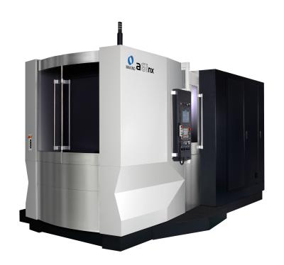
Makino introduces the newly updated a51nx and a61nx horizontal machining centers. With the same rigid casting and axis designs of the original platforms, the updated a51nx and a61nx feature an expanded list of technology advancements, including increased spindle torque, innovative tool monitoring, advanced motion controls and the new Professional 6 control.
“When it comes to uptime, reliability and productivity, manufacturers won’t find a more robust pair of horizontal machining centers,” said David Ward, horizontal product line manager at Makino. “The updated set of features on these machines unleashes a whole new level of productive capability that will greatly reduce cycle times and improve overall throughput, enabling companies to gain a competitive edge with the lowest possible cost per part.”
The a51nx and a61nx models boast expansive axis travels to accommodate a range of parts and more parts per fixture. The a51nx has a 560-mm (22-inch) X-axis and extended Y- and Z-axes of 640 mm (25.2 inches) for an industry-leading total axis volume of 8.1 cubic feet.
The standard a61nx has a 730-mm (28.7-inch) X-axis, 650-mm (25.6-inch) Y-axis and extended Z-axis of 800 mm (31.5 inches). An optional tall column on the a61nx expands the Y-axis to 730 mm (28.7 inches), allowing customers to process larger parts that may have previously required 50 taper machines. Thanks to the expanded Z-axis stroke, maximum tool length on the a51nx and a61nx models is increased to 430 mm (16.9 inches) and 510 mm (20.1 inches), respectively.
Spindle reliability continues with the updated a51nx and a61nx models, featuring a standard 14,000-rpm (30-kW) spindle that has been upgraded to deliver 303 Nm of duty-rated torque. This design enables the machines to accelerate and decelerate from full rpm in 17 percent less time. When compared to previous models, the additional torque reduces rigid tapping time by 20 to 25 percent per hole. Large-diameter angular contact bearings ensure the highest level of rigidity for a variety of applications and processes.
An optional 24,000-rpm (80/60-kW) spindle is available on the a61nx model for extremely high metal-removal rates in aluminum part applications. A new 20,000-rpm (30/18-kW) spindle with direct-inject air-oil lubrication is also available, delivering improved reliability and greater power for enhanced productivity.
Several enhancements have been made to reduce non-cut time on the updated a51nx and a61nx machines. A vision-type broken-tool sensor (Vision B.T.S.) comes standard, supporting unattended operation by quickly validating the condition of cutting tools after each tool change. By creating a silhouette of the cutting tools, Vision B.T.S. is also able to detect the length, size and approximate weight of the tool. This information can then be applied to automatically set the tool-change speed to the appropriate setting (fast, medium or slow). The Vision B.T.S. system has fewer moving parts and requires no physical contact with the cutting tool, allowing for enhanced, long-term reliability and less risk of chipping delicate tool materials, such as PCD.
Inertia active control (IAC) technology has also been expanded for greater efficiency on the updated a51nx and a61nx machines. In addition to optimizing positioning motion of the rotational B-axis, IAC technology is now able to improve acceleration and deceleration rates along the Z-axis—the most frequently moved axis during cutting processes. IAC has also been added to the rotation of the ring-type tool magazine. Each time tools are loaded into the magazine, IAC quickly evaluates the total weight held in the ring and adjusts acceleration to match the total load for reducing the time the tool magazine seeks tools.
With a blend of the proven stability of the FANUC hardware and Microsoft Windows Embedded Standard 7 OS, the Professional 6 control helps move operators fluidly through machine setup, empower them with easily accessible information and protect them with enhanced safety. Cycle-time saving and dynamic-control capabilities have been added to the control’s GI functions to help lower costs per part.
Two forms of advanced motion-control GI are included with the Pro6 control:
· GI Drilling is a unique G-code drilling cycle that enables the spindle and tool to arc from hole to hole instead of following a square path. This simple change reduces non-cut time by as much as 15 percent on common hole-pattern drilling.
· GI Milling is designed to improve performance in 2-D milling. GI Milling lets the user define a corner-rounding tolerance on each milling path. Even a small tolerance enables the machine to quickly flow through the cut path, completing milling paths in less time.
On complex 2-D paths, testing has reduced cut time up to 35 percent. While not every tool can make use of these functions, advanced motion control GI is proven to reduce overall cycle time by 3 to 8 percent in typical production components. This reduction saves substantial cost in both high-volume and low-volume production environments by reducing the number of spindles required and freeing up machine availability to take on more work.
The exterior of the machines have evolved in an effort to make maintaining the machine easier for the operator. An L-shaped door, when open, allows more light to enter the machine and prevents fluid from dripping onto the operator during inspection and maintenance. The wide opening on the pallet-loading station doors lends easy access for loading of fixtures and large workpieces. This type of accessibility is crucial for part loading and unloading in robot-automated environments.
Chip and coolant management has been improved with the addition of a standard hydro-cyclonic filtration system. This system cleans coolant down to a 20 μm level, extending the maintenance life of the coolant.
Contact Details
Related Glossary Terms
- 2-D
2-D
Way of displaying real-world objects on a flat surface, showing only height and width. This system uses only the X and Y axes.
- centers
centers
Cone-shaped pins that support a workpiece by one or two ends during machining. The centers fit into holes drilled in the workpiece ends. Centers that turn with the workpiece are called “live” centers; those that do not are called “dead” centers.
- coolant
coolant
Fluid that reduces temperature buildup at the tool/workpiece interface during machining. Normally takes the form of a liquid such as soluble or chemical mixtures (semisynthetic, synthetic) but can be pressurized air or other gas. Because of water’s ability to absorb great quantities of heat, it is widely used as a coolant and vehicle for various cutting compounds, with the water-to-compound ratio varying with the machining task. See cutting fluid; semisynthetic cutting fluid; soluble-oil cutting fluid; synthetic cutting fluid.
- fixture
fixture
Device, often made in-house, that holds a specific workpiece. See jig; modular fixturing.
- gang cutting ( milling)
gang cutting ( milling)
Machining with several cutters mounted on a single arbor, generally for simultaneous cutting.
- milling
milling
Machining operation in which metal or other material is removed by applying power to a rotating cutter. In vertical milling, the cutting tool is mounted vertically on the spindle. In horizontal milling, the cutting tool is mounted horizontally, either directly on the spindle or on an arbor. Horizontal milling is further broken down into conventional milling, where the cutter rotates opposite the direction of feed, or “up” into the workpiece; and climb milling, where the cutter rotates in the direction of feed, or “down” into the workpiece. Milling operations include plane or surface milling, endmilling, facemilling, angle milling, form milling and profiling.
- polycrystalline diamond ( PCD)
polycrystalline diamond ( PCD)
Cutting tool material consisting of natural or synthetic diamond crystals bonded together under high pressure at elevated temperatures. PCD is available as a tip brazed to a carbide insert carrier. Used for machining nonferrous alloys and nonmetallic materials at high cutting speeds.
- tapping
tapping
Machining operation in which a tap, with teeth on its periphery, cuts internal threads in a predrilled hole having a smaller diameter than the tap diameter. Threads are formed by a combined rotary and axial-relative motion between tap and workpiece. See tap.
- tolerance
tolerance
Minimum and maximum amount a workpiece dimension is allowed to vary from a set standard and still be acceptable.