Cross-hole drilling can test a machinist's mettle.
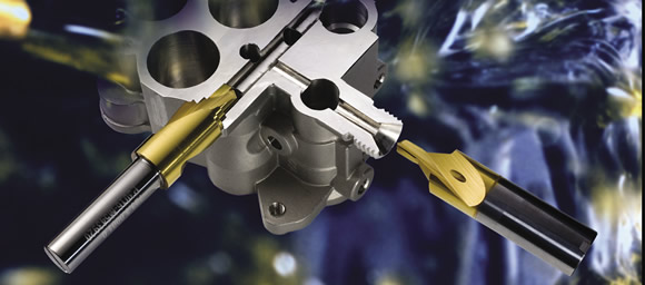
Courtesy of Mikron Corp. Monroe
Porting operations in a cross-drilled manifold block.
Drilling cross-holes in some parts is no big deal. These are often simple parts, such as aluminum valve bodies, where the holes aren’t too deep and meet on-center, and the customer can live with a small burr at the intersection.
On the other end of the spectrum are P-2 tool steel injection molds for complex medical devices, with more holes than a block of Swiss cheese and tolerances that make even veteran machinists weep.
Even simple cross-hole drilling presents challenges, including high tool wear, poor chip evacuation, difficult-to-remove burrs and tool deflection that can snap the toughest of drills. But there are ways to turn the bane of holemaking into a more bearable task.
It’s in the Geometry
According to Dan Habben, applications engineer at Sumitomo Electric Carbide Inc., Mt. Prospect, Ill., cross-holes are always a problem child. “Probably the best tip I can give is this: don’t do it!” laughed Habben, who works with automotive suppliers and sees cross-holes in everything from transmission housings to hydraulic valves for diesel engines. “Our customers cut a lot of die-cast aluminum and gray cast iron, and one of the main problems we see, especially with aluminum, is burrs. In hydraulic systems, it’s important to get a clean hole. Any chips or hanging chads left in the workpiece might pass into the hydraulics, damaging a valve or pump.”
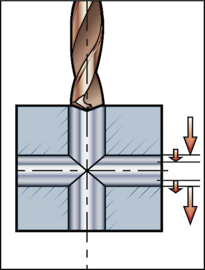
Courtesy of Sandvik Coromant
When entering and exiting a cross-hole, Sandvik Coromant recommends reducing the feed to a quarter of the normal rate.
One possible cure is effective edge preparation on the drill, together with appropriate feed and speed modifications. “We usually recommend a corner clip in this case,” Habben said, “meaning a 45° chamfer on the outer margin of the drill, together with a small edge prep, say, a light T-land or a hone of around 0.003 " to 0.004 " on the cutting edge. And it’s especially important to use a sharp tool.”
Matt Sippel, senior product application engineer at Melin Tool Co., Cleveland, agreed: “The one big thing we’ve been doing for cross-hole drilling is putting a special geometry on our coolant-fed drills. The tip tends to be a little bit flatter, say, around 140°, with a slight chamfer on the outside edge, and sometimes an edge prep. This is an old trick in the aerospace industry. It tends to protect the corner of the drill as you break through into the intersecting hole.”
Habben said this is just part of the story, though. “As the drill tip breaks through into the intersecting hole, a rule of thumb would be to decrease the feed rate by about 50 percent. This helps minimize the number of burrs and also to reduce deflection, especially in an off-center situation.”
Also, examine the drilling sequence. “A lot of valve bodies use a porting tool for the valve seat, then a small cross-hole for the hydraulics, which is usually off-center. Correct processing of the part would be critical in this situation,” Habben said. “For example, the small-diameter holes for the hydraulics you would want to do first, and then go in with the porting tool after, because the larger tool is generally shorter and can handle the deflection better.”
Breaking Through
No edge prep in the world, however, will help without a good drill. The cutting forces generated on breakthrough when cross-hole drilling can be tremendous, and deflection becomes a real problem. Al Zaitoon, sales and marketing manager for YG-1 Tool Co., Vernon Hills, Ill., explained that indexable-insert drills, or insert drills, a staple in most machine shops, are not the answer for cross-hole drilling.
“You need some sort of support to keep the drill stable when you break through into the cross-hole,” Zaitoon said. “With an insert drill, there’s no margin behind the cutting edge to stabilize it like there is with other drills.”
Zaitoon painted this picture of a typical cross-hole. “Say you’re using a ½ " solid-carbide drill to go into a 3⁄8" cross-hole and it passes into another hole after that. The drill has a margin length of 2 " or maybe 3 ", so that helps stabilize it as it passes from one hole to the next. You don’t have that with a spade or insert drill. They end up just bouncing around.”
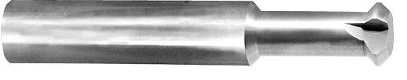
Courtesy of Mitsubishi Materials USA
Mitsubishi says it through-coolant, solid-carbide, double-margin drill achieves optimal chip evacuation when cross-hole drilling.
Sumitomo’s Habben seconded Zaitoon. He suggested that insert drills are bad juju on cross-hole drilling and recommends solid-carbide and replaceable-tip drills instead. “Insert drills are not very good on cross-holes because they have a single effective cutting edge and tend to deflect,” he said.
Habben added that for holes below ½ " in diameter, “solid carbide is the only way to go.” However, he warned, anything much larger than this and you could be talking serious cash, whereas a replaceable-tip drill is about half the cost and as accurate. Habben said: “A lot of cross-holes are deep, maybe 12 to 20 times diameter. With hole sizes running anywhere from 1⁄8" to 1 " or more, solid-carbide tools this long can get expensive, especially for large holes. You can easily spend $500 to $800 per drill.”
Replaceable-tip drills have basically the same geometry as solid-carbide drills, with two effective cutting edges in a one-piece design. The head is secured with screws against a ground serration. This offers high locational accuracy as well as strength in the drive mechanism, according to Habben.
Other Ways to Improve
Some additional items in the cross-hole drilling first-aid kit are advanced coatings and lots of coolant because the process can generate a lot of heat. “Coatings help, because many times in cross-hole drilling you’re running at a reduced feed rate, which means poor chip formation,” Habben said. He noted Sumitomo offers a polished, TiAlCr coating just a few microns thick. “It uses nano-coating technology, meaning the coating is applied in extremely thin layers. This makes it very lubricious and significantly less expensive than a diamond coating, while offering comparable tool life.”
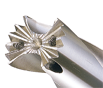
Courtesy of Melin Tool
A Melin multiflute cutter removes difficult burrs using a CAM-generated toolpath, according to the company.
Chip evacuation is critical, according to Habben. “High-pressure coolant above 600 psi is recommended to flush those chips out. And when you get into larger holes, say, above 3⁄8" in diameter, it’s important to have a pump that can handle the increased volume. Figure on 5 to 10 gpm for ½ "-dia. holes and up to 15 to 20 gpm on larger holes. That will give you the volume needed to overcome the fluid loss when you break through into the cross-hole.”
Habben made a final point, one that machinists often overlook. TIR, or total indicator runout, should be less than 0.001 " and preferably better than 0.0005 "—a critical characteristic for improved tool life and hole accuracy. That might sound like a tall order to many shops, but Habben argued it is easily achieved with high-quality hydraulic or shrink-fit toolholders.
In Spades
Rob Brown, product manager for Allied Machine & Engineering Corp., Dover, Ohio, agreed with most of that advice. “As far as insert drills go, they’re absolutely right. There’s no margin on those tools and only a single effective cutting edge. On spade drills, however, the margin runs the length of the insert itself. Sure, that’s all the support you’re going to get, but it’s still a lot more than you’d get with an insert drill.”
In cases where this doesn’t quite cut the mustard, Brown recommends a special, where the body of the drill has guides to help stabilize it through the interruption.
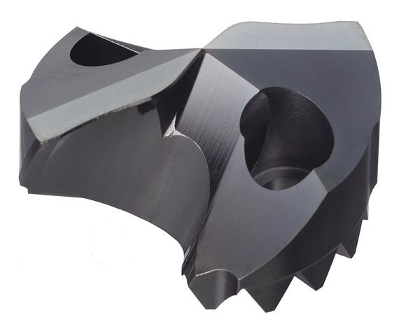
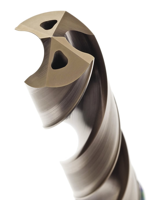
Courtesy of Sumitomo Electric Carbide
An aggressive cutting head (top) is rigidly clamped to a through-coolant drill shank on Sumitomo’s SMD-style replaceable-tip drill.
For the most part, though, Brown said spade drills are just the ticket for holes 3⁄4 " in diameter and larger. “It’s application-dependent, but we will typically go in with a spade drill, because most of the time with cross-hole drilling you’re talking about a deeper hole. Spade drills are more cost-effective than either indexable-insert or solid-carbide drills. We offer HSS and carbide spade bits. If you’re in a situation where there’s a lot of shock or inconsistency in the workpiece material, we’d recommend HSS because it absorbs shock a lot better than carbide. But if the shop has a good setup and productivity is important, you’ll be looking at a carbide tip.”
Like his competitors, Brown said edge preparation is key. “We grind a chamfer, what we call an SK2 corner clip, on the outer margin of the drill. This helps stabilize the tool while improving tool life and reducing burr formation. From a cross-hole standpoint, the secret is in the stability of the tool.”
And there’s no argument on feeds and speeds. “Until you get to the cross-hole, you’re going to run the recommended feeds and speeds,” Brown said. “If it’s a really deep hole, you have to go a bit lighter. As a rule, we tell people to reduce the feed rate when cross-hole drilling. The problem is that you give up good chip formation when you do that, but you help ease the transition into the cross-hole. And once you engage fully on the other side of the hole, you can go back to normal.”
Make Up Your Mind
The on-again, off-again nature of cross-hole drilling introduces yet another challenge. “Cross-holes are difficult from a programming standpoint,” said Product Specialist Nika Alex at Mitsubishi Materials USA Corp., Fountain Valley, Calif. “Because you’re constantly entering and exiting the workpiece, you have to speed up and slow down accordingly. And since most of these holes are quite deep, you’re working with a very long drill, which usually means using a short drill to get the hole started and switching to a longer one mid-cycle. That can mean vibration and flex until the tool is fully engaged—if so, try reducing speed momentarily.”
Like his peers, Alex suggested reducing the feed by at least half when breaking into the cross-hole. “Once you’re in the clear, you can go faster, at least until the far side of the cross-hole. That’s where I recommend really dropping the feed rate, maybe a thou or two per rev, so the drill doesn’t walk. Finally, once the point angle is fully engaged, you should immediately increase the feed rate again so you don’t have chip control issues.”
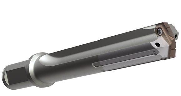
Courtesy of Allied Machine & Engineering
A custom spade drill from Allied Tool offers long margins for additional support when cross-hole drilling.
Hans Liechti of Mikron Tools sees things differently. While he acknowledges the complexities of cross-hole drilling, Liechti said CAM software should have no problem calculating the proper toolpath. “It’s not as much of a big deal as it once was.”
Liechti is manager of the cutting tool division at Mikron Corp. Monroe, Monroe, Conn., which specializes in tools smaller than 6mm in diameter. This means a lot of solid-carbide, coolant-fed drills as well as custom step tools, reamers and porting tools.
Ask Liechti which tool is best for cross-holes and he’ll probably say something crazy. “Our standard line of tools is called the Crazy Drill.” You can’t help but ask why. “We developed a special drill for a customer. When he came in for the runoff demo, we exceeded his expectation by two times. He said those tools cut like crazy.”
Despite an unorthodox name, the Crazy Drill has all the requirements needed when it comes to cross-hole drilling, with a 140° drill tip, double-margin flutes and a coolant-fed, solid-carbide body. “You can be quite aggressive with these tools, up to five times the typical feed rate, then slow down as you break through into the cross-hole.”
According to Liechti, the biggest problem with cross-hole drilling is when the holes are extremely off-center. “All our tools are carbide, so they’re fairly stiff, but if the two holes are very off-center to one another, there’s a risk of tool breakage,” he said. “In that case, we recommend going in with a wider point angle, almost like an endmill, to get the far side of the hole started.”
Despite the competitive nature of cutting tool manufacturers, there’s a lot of consensus on cross-hole drilling recommendations, and most companies agree with the following advice:
• Buy high-quality solid-carbide drills, followed by replaceable-tip or spade drills—no insert drills.
• Use high-pressure, high-volume coolant to promote chip evacuation, reduce heat and lubricate the cutting tool.
• Learn the cross-hole programming two-step, juggling feeds and speeds to keep holes straight and avoid broken cutting tools.
• A honed edge with a corner clip on the outer margin of the drill reduces burr formation and makes tools last longer.
• Use a rigid setup and process holes in the order that best avoids tool deflection.
Cross-hole drilling is challenging work, but these tips should point you in the right direction. If not, call your cutting tool rep. You’ll be crossing holes in record time. CTE
About the Author: Kip Hanson is a contributing editor for CTE. Contact him at (520) 548-7328 or [email protected].
Tangling with those nasty burrs in cross-holes
Making the hole is sometimes the easiest part of cross-hole drilling. “We have customers that once took 10 hours to deburr hydraulic manifolds filled with dozens of holes,” said Stan Kroll, sales manager at J.W. Done Corp., Hayward, Calif. “And with one slip of the blade, the part was scrapped.”
Kroll and J.W. Done President Michael Kapgan will tell you the Orbitool deburring device eliminates the craft factor of manual deburring. “You can literally do it with your eyes closed,” Kapgan said. “It greatly simplifies the manual deburring process. You just run it in and out of the hole, like you’re playing a violin.”
That’s music to anyone’s ears. J.W. Done guarantees its product, whether it’s used to replace traditional manual deburring processes or in a CNC machine tool. “People ask us why we don’t have any product returns,” Kapgan said. “I tell them it’s because we don’t give a return address.”
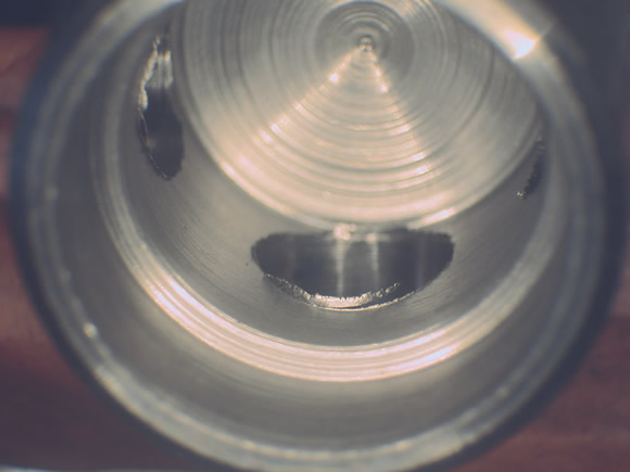
Courtesy of J.W. Done
Before: Burrs surround cross-holes in this piston body.
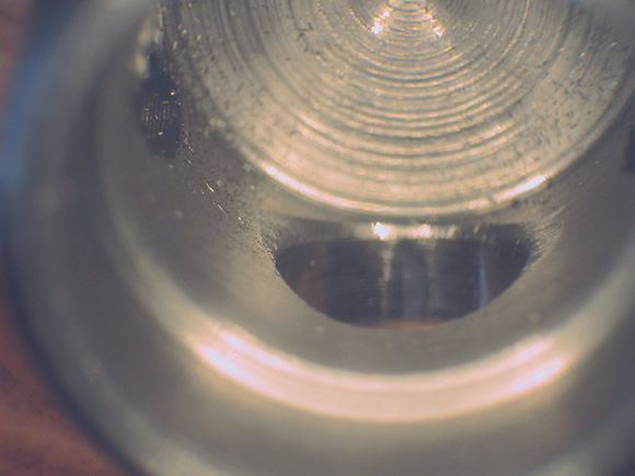
Courtesy of J.W. Done
After one pass with an Orbitool deburring tool, the hole is burr-free with a radiused edge.
All kidding aside, the product works through a patented mechanism utilizing a flexible shaft together with a polished disk that acts like a cam follower against the hole wall, allowing the Orbitool to cleanly and effectively remove cross-hole burrs.
The amount of edge break is controlled by the preload on the tool together with simple programming techniques, providing anything from a sharp, burr-free edge to a large radius. “It’s just like milling a thread,” Kroll said. “We tell the tool the diameter of the hole and how deep to go. Orbitool takes care of the rest.”
View a product demonstration at www.youtube.com/user/JWDoneOrbitool.
—K. Hanson
Contributors
Allied Machine & Engineering Corp.
(800) 321-5537
www.alliedmachine.com
J.W. Done Corp.
(888) 535-3663
www.jwdone.com
Melin Tool Co.
(800) 521-1078
www.endmill.com
Mikron Corp. Monroe
(203) 261-3100
www.mikron.com/tool-us
Mitsubishi Materials USA Corp.
(800) 523-0800
www.mitsubishicarbide.com
Sumitomo Electric Carbide Inc.
(800) 950-5202
www.sumicarbide.com
YG-1 Tool Co.
(800) 765-8665
www.yg1usa.com
Contact Details
Contact Details
Contact Details

Contact Details
Contact Details
Contact Details
Contact Details

Related Glossary Terms
- burr
burr
Stringy portions of material formed on workpiece edges during machining. Often sharp. Can be removed with hand files, abrasive wheels or belts, wire wheels, abrasive-fiber brushes, waterjet equipment or other methods.
- computer numerical control ( CNC)
computer numerical control ( CNC)
Microprocessor-based controller dedicated to a machine tool that permits the creation or modification of parts. Programmed numerical control activates the machine’s servos and spindle drives and controls the various machining operations. See DNC, direct numerical control; NC, numerical control.
- computer-aided manufacturing ( CAM)
computer-aided manufacturing ( CAM)
Use of computers to control machining and manufacturing processes.
- coolant
coolant
Fluid that reduces temperature buildup at the tool/workpiece interface during machining. Normally takes the form of a liquid such as soluble or chemical mixtures (semisynthetic, synthetic) but can be pressurized air or other gas. Because of water’s ability to absorb great quantities of heat, it is widely used as a coolant and vehicle for various cutting compounds, with the water-to-compound ratio varying with the machining task. See cutting fluid; semisynthetic cutting fluid; soluble-oil cutting fluid; synthetic cutting fluid.
- edge preparation
edge preparation
Conditioning of the cutting edge, such as a honing or chamfering, to make it stronger and less susceptible to chipping. A chamfer is a bevel on the tool’s cutting edge; the angle is measured from the cutting face downward and generally varies from 25° to 45°. Honing is the process of rounding or blunting the cutting edge with abrasives, either manually or mechanically.
- endmill
endmill
Milling cutter held by its shank that cuts on its periphery and, if so configured, on its free end. Takes a variety of shapes (single- and double-end, roughing, ballnose and cup-end) and sizes (stub, medium, long and extra-long). Also comes with differing numbers of flutes.
- feed
feed
Rate of change of position of the tool as a whole, relative to the workpiece while cutting.
- flutes
flutes
Grooves and spaces in the body of a tool that permit chip removal from, and cutting-fluid application to, the point of cut.
- gang cutting ( milling)
gang cutting ( milling)
Machining with several cutters mounted on a single arbor, generally for simultaneous cutting.
- high-speed steels ( HSS)
high-speed steels ( HSS)
Available in two major types: tungsten high-speed steels (designated by letter T having tungsten as the principal alloying element) and molybdenum high-speed steels (designated by letter M having molybdenum as the principal alloying element). The type T high-speed steels containing cobalt have higher wear resistance and greater red (hot) hardness, withstanding cutting temperature up to 1,100º F (590º C). The type T steels are used to fabricate metalcutting tools (milling cutters, drills, reamers and taps), woodworking tools, various types of punches and dies, ball and roller bearings. The type M steels are used for cutting tools and various types of dies.
- milling
milling
Machining operation in which metal or other material is removed by applying power to a rotating cutter. In vertical milling, the cutting tool is mounted vertically on the spindle. In horizontal milling, the cutting tool is mounted horizontally, either directly on the spindle or on an arbor. Horizontal milling is further broken down into conventional milling, where the cutter rotates opposite the direction of feed, or “up” into the workpiece; and climb milling, where the cutter rotates in the direction of feed, or “down” into the workpiece. Milling operations include plane or surface milling, endmilling, facemilling, angle milling, form milling and profiling.
- point angle
point angle
Included angle at the point of a twist drill or similar tool; for general-purpose tools, the point angle is typically 118°.
- shank
shank
Main body of a tool; the portion of a drill or similar end-held tool that fits into a collet, chuck or similar mounting device.
- spade drill
spade drill
Flat end-cutting tool used to produce holes ranging from about 1" to 6" in diameter. Spade drills consist of an interchangeable cutting blade and a toolholder that has a slot into which the blade fits. In horizontal applications, universal spade drills can achieve extreme depth-to-diameter ratios, but, in vertical applications, the tools are limited by poor chip evacuation.
- toolpath( cutter path)
toolpath( cutter path)
2-D or 3-D path generated by program code or a CAM system and followed by tool when machining a part.
- total indicator runout ( TIR)
total indicator runout ( TIR)
Combined variations of all dimensions of a workpiece, measured with an indicator, determined by rotating the part 360°.
- total indicator runout ( TIR)2
total indicator runout ( TIR)
Combined variations of all dimensions of a workpiece, measured with an indicator, determined by rotating the part 360°.
Author

Kip Hanson is a contributing editor for Cutting Tool Engineering magazine. Contact him by phone at (520) 548-7328 or via e-mail at [email protected].