New materials, the need for lightweight parts and the burgeoning size of some aircraft challenge manufacturers of landing gear components.
Sleek wings and powerful engines are familiar images of flight. An aircraft’s landing gear, however, is just as essential for successful air travel. A fully loaded, double-deck, 800-passenger Airbus A380 jetliner weighs about 1.3 million lbs. Aloft, those 650 tons are supported by the magic of aerodynamic lift. But movement on the ground, including takeoff and landing, are handled by components that are complex, remarkably strong and quite large.
For example, Goodrich Corp., Charlotte, N.C., said the undercarriages for the main landing gear it supplies for the A380 are 18½ ' tall. As the size of some aircraft grows and demand for fuel efficiency increases across the board, manufacturers of landing gear face the challenge of making the large, complex assemblies both as strong and as light as possible.
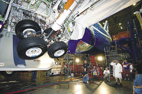
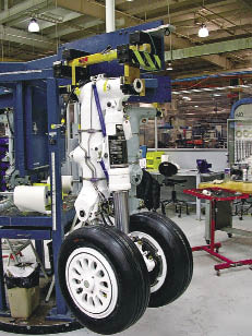
Courtesy of Boeing
A landing gear test on the Boeing 787 Dreamliner.
Like all manufacturers, landing gear makers are dealing with supplier consolidation and implementation of lean initiatives. Said John Cerps, manufacturing engineering manager at the Toronto facility of global landing gear provider Messier-Dowty International, Vélizy, France, “over the last 5 to 10 years, there has been a major transition for all major subsystem suppliers to airframe manufacturers. Everyone is trying to offer an integrated system as opposed to individual parts or subassemblies.”
Cerps said Messier-Dowty Inc. works with its customers to determine the space available for the landing gear, the desired configuration and functional details, and then provides a plug-in solution. “We are giving them the landing gear system,” Cerps said, “which is all the electrics, hydraulics and pneumatics, complete with wheels, brakes and tires, the steering system and braking system. The landing gear is bolted into the aircraft and all they have to do is connect the electrics, hydraulics and pneumatics.”
Cerps estimates that the Toronto facility, whose capabilities include design, development, production and support of landing gear for military, business and commercial aircraft, manufactures about 10 percent of the parts for the systems it provides. For the rest, it relies on a network of proven suppliers. Cerps said his facility machines “all of the parts that are very complex, which require an investment in specialized machine tools.”
Courtesy of Messier-Dowty
This business jet’s main landing gear is typical of the integrated landing gear systems provided by Messier-Dowty.
Also like other manufacturers, Messier-Dowty is “in competition with ourselves; we are mandated by our corporate head offices to continually improve,” Cerps said. For example, he described efforts to optimize production of a family of landing gear components consisting of four pistons and four cylinders. Based on lean manufacturing principles, Messier-Dowty created an autonomous cell consisting of two lathes, a 3-spindle vertical machining center with an automatic 4th-axis indexing fixture and a 3½-axis horizontal machining center. “One of the flatbed lathes was set up for external work and the other was set up for internal work,” Cerps said, who added that the arrangement greatly reduced setup time because the machines didn’t have to be reconfigured individually to handle those operations. “The guys in the cell received cross training, employed pull systems and followed all the rules of Kanban,” he added. In addition to speeding throughput, the work also helped assure part-to-part consistency by simplifying machine-to-machine transition of the parts.
The basic elements of an aircraft landing gear are the major support component, called the main or center fitting; the piston, or slide, that goes into the center fitting and provides the ability to lower and raise the gear; and the truck, or bogie beam, which is the crosspiece through which the axles run. The assembly also includes various small support struts, linkages and actuators. Until recently, ultrahigh-strength steels (such as 300-M, a high-tensile modified 4340 alloy) and aluminum alloys were the main materials employed. Now, to meet fuel economy-driven weight reduction requirements while maintaining strength, titanium and composites are being introduced. For example, the Boeing 787’s main landing gear, produced by Messier-Dowty, includes ultrahigh-strength steel components, a titanium slider and braces made of composites. Messier-Dowty said it evaluated the manufacture of landing gear components from titanium matrix composites. Those materials exceed the performance of 300-M steel and titanium through a combination of strength, durability and light weight, but high material and manufacturing costs presently exclude their application.
Simultaneous Strategy
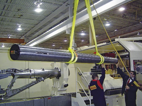
The time required to machine landing gear components, especially large parts, is remarkable. Mike Zambenedetti, senior application engineer for machining systems supplier MAG Cincinnati, Hebron, Ky., said a typical large landing gear component can be 150 " long and require processing on a series of five to 10 different machine tools. The high-strength alloy steel and titanium parts begin as rough forgings and machining times for each part are lengthy: total OD roughing can consume 200 hours, finishing can add 240 hours and ID operations may take 200 hours.
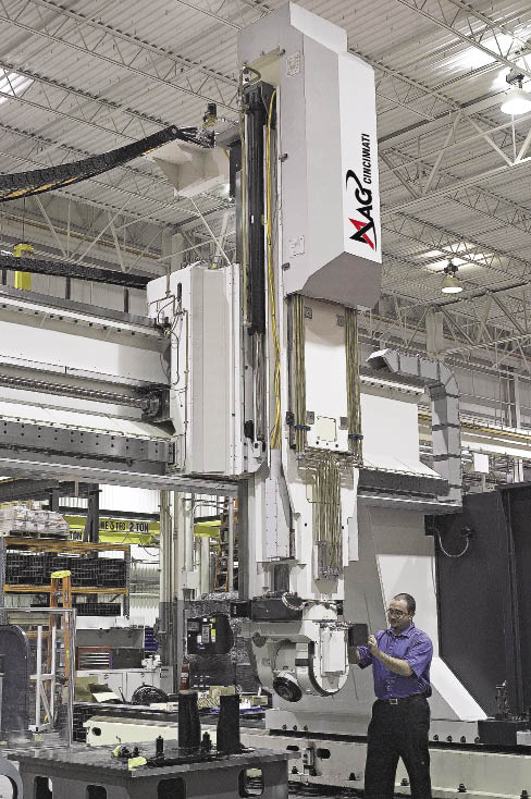
Courtesy of MAG Cincinnati
Top: A technician performs maintenance on a U5 single-spindle, 5-axis machining center from MAG Cincinnati. This configuration provides the flexibility and Z-stroke capacity required to access certain features on landing gear components.
Below: A titanium aircraft landing gear bogie beam fixtured for finishing operations in a U5 single-spindle, 5-axis machining center.
Mike Sess, MAG application engineering and vertical machine platform manager, said a key to maximizing throughput of the large parts is simultaneous machining. To facilitate that, MAG supplies multispindle, multiaxis profiling machines in which the spindles follow identical paths. In a 5-axis, 5-spindle profiler, for example, all five spindles move on the same X, Y, Z, A and B axes. “They are all carried in the same ‘bathtub,’ as we call it,” Sess said. The spindles are programmed to work on five identical parts simultaneously, reducing the total time required to perform an operation on the parts by 80 percent compared to a single-spindle arrangement.
Courtesy of MAG Cincinnati
In a 5-axis, 5-spindle profiler supplied by MAG Cincinnati, all five spindles move on the same X, Y, Z, A and B axes, follow identical paths and are programmed to work on five identical parts simultaneously.
The machines optimize workhandling as well. A 5-spindle profiler can feature an X-axis stroke of 144 ', which, according to Zambenedetti, enables the manufacturer to set up zones where parts can be loaded or unloaded while other parts are being machined.
Illustrating the aerospace industry’s demand for such machine tools, MAG Cincinnati is scheduled to deliver $70 million of equipment to the world’s largest producer of titanium, VSMPO-Avisma, for a global “Landing Gear Manufacturing Center for Excellence” in Verkhnaya Salda, Russia. The order includes four multispindle titanium profilers and 12 HMCs, as well as workhandling and control equipment. The facility will produce landing gear components for the Boeing 787 and 777, the Airbus A380 and A350WXB and the Sukhoi Superjet 100. MAG Cincinnati’s shipment follows its delivery of 10 titanium machining systems to VSMPO and its neighboring Boeing joint-venture company, Ural Boeing Manufacturing.
The size and capability of aerospace machining systems have evolved in tandem with changes in aircraft components, Sess said. In a response to growing use of titanium alloys for landing gears, enhancements to MAG profilers include spindles with torque output in the range of 2,000 lbs.-ft., application of the heavy-duty HSK 125 toolholders and design features that increase the machines’ stiffness and rigidity.
As for smaller landing gear components, they benefit from mill/turn centers. Although those machine tools generally possess a smaller swing capacity than massive single-purpose equipment and therefore are limited to smaller parts, the centers reduce setup times “drastically because you can do multiple operations in one setup,” said Peter Bhavra, tooling engineering specialist at Messier-Dowty in Toronto. Bhavra said the facility is adding two multitask machines to the mill/turn equipment it already has and plans to move currently produced parts to the new machines to optimize production and further improve consistency of part quality.
Tooling Package
Chris Mills, U.S. senior project manager of aerospace development for toolmaker Sandvik Coromant Co., Fair Lawn, N.J., said the unique features of and materials for landing gear components has prompted development of specialized aerospace tooling. For example, he said, Sandvik Coromant has assembled a package of tools for the key operations in landing gear machining, including deep-hole drilling, external profiling, 2-D and 3-D turn/milling, trepanning and helical interpolation. When manufacturing landing gear components from forgings, he said, “there is a huge amount of material that is removed,” adding that when machining is completed, often just 10 to 20 percent of the forging’s original weight remains.
Mills said perhaps the most challenging operation is drilling deep, large-diameter holes. “Some of the holes down the middle of a component are over 1 ' in diameter and 6 ' in depth.”
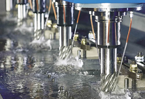
Courtesy of Sandvik Coromant
For deep-hole drilling operations on large landing gear components, Sandvik Coromant developed T-Max special drill heads for diameters from 100mm to 358mm. The heads are designed to work with high-pressure, high-volume coolant systems. To facilitate chip removal in deep bores, the coolant is routed to the cutting drill’s cutting edges and then flows back through the drill body itself.
For large landing gear components, deep-hole drilling often is performed on specialized machines. To make deep holes with the special machines, Mills said Sandvik Coromant developed T-Max special drill heads for diameters from 100mm to 358mm. Exchangeable cartridges and shims enable the head to be adjusted to produce different diameters.
The heads work with high-pressure, high-volume coolant systems. Unlike the coolant path in a typical through-coolant tool, in which coolant flows through the drill tip and out of the hole past the outside of the drill shaft, in the big drilling heads the coolant is routed to the cutting drill’s cutting edges and then flows back through the drill body itself to enhance chip removal from deep holes. To maintain concentricity, wear pads are situated on the drill’s OD. The tendency of titanium to chemically combine with cutting tool materials dictates the wear pad design and compositions. “The wear pads need to be smooth, have good lubricity, and not have reaction at all with the material,” Mills said.
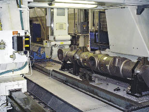
Courtesy of Sandvik Coromant
Bores produced by deep-hole drilling usually require the machining of internal features. Special boring bars with antivibration packages, such as this TNS bar from Sandvik Coromant, cut productively at long depth-to-diameter ratios. This 8.66 "-dia. bar was employed to machine a 12 "-dia. bore 8 ' deep in a landing gear component made of 300-M alloy steel.
Bores produced when deep-hole drilling usually require various internal features. To produce these features with the desired precision at high depth-to-diameter ratios, “you need antivibration bars,” he said. The toolmaker’s TNS bars, for example, feature an internal devibration package consisting of a slug suspended in oil. Often, for added rigidity, such bars are made of carbide.
As an example of a typical application for devibration bars, Mills described a landing gear boring operation in 300-M steel that involved an 8.66 "-dia. bar machining a 12 "-dia. bore 8 ' deep. For roughing, the tooling was able to achieve a cutting speed of 305 sfm, a feed rate of 0.016 ipr and a 0.197 " DOC, and finishing at the same cutting speed, a 0.008- ipr feed and a 0.047 " DOC.
Tooled to Fit The Job
To improve throughput, some landing gear manufacturers purchase forgings with excess material removed in a process referred to as forging qualification. Qualification usually includes roughing and finishing internal cylinder bore features and selected key locating surfaces.
A supplier of qualified forgings, Ewart-Ohlson Machine Co., Cuyahoga Falls, Ohio, specializes in CNC machining of medium to large parts in both standard and exotic alloys for the aerospace, energy, steel and automotive industries. David Achauer, the shop’s general manager, said landing gear customers come to Ewart-Ohlson for its combination of large boring mills, large-swing lathes, deep-hole drilling equipment and experience in processing large, difficult-to-handle parts. He described the company’s business as “varying from fast, heavy material removal to precision machining, depending upon product requirements. One of our core competencies is machining large cylinders, pistons or tubes, including landing gear components.”
The largest examples of forgings qualified at Ewart-Ohlson are approximately 130 " long and weigh about 12,000 lbs. Most of the parts are aircraft-grade high- tensile steel, such as 300-M, but the shop also machines titanium and aluminum. Qualification typically includes establishing end-product centerlines within the forging envelope, roughing and/or finishing a large percentage of deep bores and machining locating surfaces that allow landing gear manufacturers to locate the forging for profiling.
To drill, bore and form deep holes in the forgings, the shop fabricates much of its own tooling, including boring bars, carbide drilling and boring heads, form cutters and locating fixtures. Ewart-Ohlson uses specialty machines with the horsepower and torque required for maximum material-removal rates, high-pressure coolant to maintain tool life and fixturing and tooling that can achieve straightness over the length of the bore. The largest holes drilled in landing gear components are about 10 ' deep and 15 " in diameter.
Turning operations are performed on large, powerful machines such as a 200-hp SAFOP Leonard 1000/1800 lathe, which can swing parts up to 98.5 " in diameter (65 " over the cross slide), 21 ' long and weighing 40 tons. Counterweighting the large, eccentrically shaped workpieces is critical to spin the parts smoothly and hold diametrical and roundness tolerances of ±0.001 " over the length of a cylinder or piston.
Continuous Improvement
Likewise, Messier-Dowty’s Toronto facility also regularly tests new tooling and processes to improve its end products. The tests don’t occur in the course of regular production. “I have blocks of material and bar stock, or actual parts that for one reason or another may have been scrapped,” Bhavra said. “I maintain those so we have an actual part to use if I am going to do some test cutting.”
Bhavra described the shop’s success in developing processes for machining Aermet 100, an ultrahigh-strength martensitic alloy steel developed by Carpenter Technology Corp., Wyomissing, Pa., specifically for military landing gear applications. The alloy has high-tensile strength, fracture toughness and resistance to fatigue, all characteristics that make it difficult to machine. “When we started, we were given guidelines from another shop that recommended using cobalt, nonindexable tools, cutting it at turtle speeds and using plenty of coolant,” Bhavra said. Following development of its own machining methods, the shop now cuts the alloy with high-positive geometry indexable cutting tools, and sometimes without coolant. “There are certain things that are correct in the textbook, but when you are actually machining parts, it is totally the opposite,” Bhavra said.
Aero Tolerances
Like many aerospace components, landing gears are machined to close tolerances. According to Bhavra, they are generally machined from ±0.03 " down to ±0.0005 " depending on fit, form or function. “Bores and faces where there are mating parts, bushings for high-tolerance pins and so forth, can go as tight as ±0.0005 ",” he said. Some parts require 100 percent coordinate measuring machine inspection.
Messier-Dowty’s Cerps noted that customers’ specifications dictate that mating-part dimensions be met with cutting and grinding performed after heat treatment. For the high-tensile steels machined at the Toronto facility, post-heat-treatment hardness can be from 52 to 55 HRC.
To improve productivity, the shop may replace some grinding operations with hard turning. Parts requiring plating traditionally were hard turned and then ground before plating. Finish grinding followed the plating process. Now, Messier-Dowty wants to eliminate one of those steps. “We are trying to replace the preplate grinding with hard turning and then go straight to plating,” Cerps said.
In a related coating development, Cerps said Messier-Dowty is progressively implementing an HVOF (High-Velocity Oxygen Fuel) process to replace hard-chrome applications. HVOF uses metal-ceramic powder sprayed at 3,000 km/hr. on landing gear components, where it consolidates to form a friction- and wear-resistant coating. The environmentally friendly process eliminates the use of hexavalent chromium in the hard-chrome plating process. HVOF is in use on several production programs throughout Messier-Dowty, including the A380 nose landing gear.
Cerps pointed out that today, top quality, ease of use, ease of maintenance and lowest possible cost are givens for any manufacturer. Likewise, common goals include manufacturing products that are as light, as small and as strong as possible. But landing gear has another requirement. Unlike many of an airplane’s assemblies, the landing gear shows when the plane is on the ground. “It has to look good,” Cerps said. CTE
About the Author: Bill Kennedy, based in Latrobe, Pa., is contributing editor for Cutting Tool Engineering. He has an extensive background as a technical writer. Contact him at (724) 537-6182 or by e-mail at billk@jwr.com.
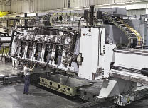
Courtesy of B. Kennedy
Multispindle profiling machines like this are part of machining systems packages being supplied by MAG Cincinnati to Russian titanium producer VSMPO-Avisma for a global “Landing Gear Manufacturing Center for Excellence” in Verkhnaya Salda, Russia.
Courtesy of MAG Cincinnati
Hard titanium alloys can cause microfractures on the thin, sharp edges of a solid-carbide drill point. AMAMCO says that on an “S-point” drill (left) the point corners (above and to the right of the lower coolant hole, below and to the left of the upper coolant hole) are rounded, or “S” shaped, to strengthen the cutting lip, compared to the corners on a standard cam-ground point drill (right).
Toolmakers' titanium tips
Some landing gear components are now being made with 5553 titanium alloy from VSMPO of Russia. That alloy, according to Chris Mills of Sandvik Coromant, “poses a lot of machining challenges.” It is much higher in strength than the commonly used Ti6Al4V alloy, generates higher cutting temperatures and is more abrasive. With the same type of tools used for Ti6Al4V, “you reduce your cutting speed by 50 percent for 5553. So if you are cutting at 50 to 60 m/min. with 6Al4V, you are down to 25 to 30 m/min. with 5553,” he said.
Mills noted that unlike nickel-base alloys that can workharden, the heat of machining has a minimal effect on titanium. “When we’ve looked at surface integrity, different cutting parameters, different edge preps or worn inserts, they have very little effect on the titanium materials the way that they do in nickel-base alloys. You’re more concerned about getting the material off,” he said.
The high value of titanium landing gear components may dictate the choice of a machining method. Mark Hatch, thread milling manager for toolmaker Emuge Corp., West Boylston, Mass., said thread milling offers advantages over tapping, especially when machining high-value aerospace parts. Thread milling—creating a thread via helical interpolation with a thread mill of smaller diameter than the hole—eliminates the possibility of tap breakage, which can ruin a partially processed part made of a high-cost material.
According to Brad Boisher, product support manager at AMAMCO Tool, Duncan, S.C., the correct tool geometry can facilitate machining titanium. He cited his company’s “S-point” carbide drill as an example. Compared to a standard cam-ground point, the drill’s corners inside the gash (where material is removed from the point’s center to create the cutting edges at the drill’s center) are rounded, or “S” shape (photo below). “The reason you round that angle is that titanium is very hard, and solid carbide is very brittle,” Boisher said. “The sharper the angle is, the weaker the cutting lip is. It’s all about strengthening the cutting lip.” Without the rounding, “you’ll get microfractures on those sharp corners.”
He added that AMAMCO drills for titanium typically feature a narrow flute gullet and a thick drill core, design aspects for maximizing strength. For a 1 "-dia. drill for titanium, the core might comprise 40 percent of the drill tip, while for a drill designed for aluminum, the core might make up only 18 percent of the tip.
— B. Kennedy
Contributors
AMAMCO Tool
(800) 833-2239
www.amamcotool.com
Emuge Corp.
(800) 323-3013
www.emuge.com
Ewart-Ohlson Machine Co.
(888) 276-9171
www.ewart-ohlson.com
MAG Cincinnati
(859) 534-4600
cinmach.mag-ias.com
Messier-Dowty Inc.
(905) 683-3100
www.messier-dowty.com
Sandvik Coromant Co.
(800) 726-3845
www.coromant.sandvik.com/us
Related Glossary Terms
- 2-D
2-D
Way of displaying real-world objects on a flat surface, showing only height and width. This system uses only the X and Y axes.
- 3-D
3-D
Way of displaying real-world objects in a natural way by showing depth, height and width. This system uses the X, Y and Z axes.
- abrasive
abrasive
Substance used for grinding, honing, lapping, superfinishing and polishing. Examples include garnet, emery, corundum, silicon carbide, cubic boron nitride and diamond in various grit sizes.
- alloys
alloys
Substances having metallic properties and being composed of two or more chemical elements of which at least one is a metal.
- aluminum alloys
aluminum alloys
Aluminum containing specified quantities of alloying elements added to obtain the necessary mechanical and physical properties. Aluminum alloys are divided into two categories: wrought compositions and casting compositions. Some compositions may contain up to 10 alloying elements, but only one or two are the main alloying elements, such as copper, manganese, silicon, magnesium, zinc or tin.
- boring
boring
Enlarging a hole that already has been drilled or cored. Generally, it is an operation of truing the previously drilled hole with a single-point, lathe-type tool. Boring is essentially internal turning, in that usually a single-point cutting tool forms the internal shape. Some tools are available with two cutting edges to balance cutting forces.
- centers
centers
Cone-shaped pins that support a workpiece by one or two ends during machining. The centers fit into holes drilled in the workpiece ends. Centers that turn with the workpiece are called “live” centers; those that do not are called “dead” centers.
- composites
composites
Materials composed of different elements, with one element normally embedded in another, held together by a compatible binder.
- computer numerical control ( CNC)
computer numerical control ( CNC)
Microprocessor-based controller dedicated to a machine tool that permits the creation or modification of parts. Programmed numerical control activates the machine’s servos and spindle drives and controls the various machining operations. See DNC, direct numerical control; NC, numerical control.
- coolant
coolant
Fluid that reduces temperature buildup at the tool/workpiece interface during machining. Normally takes the form of a liquid such as soluble or chemical mixtures (semisynthetic, synthetic) but can be pressurized air or other gas. Because of water’s ability to absorb great quantities of heat, it is widely used as a coolant and vehicle for various cutting compounds, with the water-to-compound ratio varying with the machining task. See cutting fluid; semisynthetic cutting fluid; soluble-oil cutting fluid; synthetic cutting fluid.
- cutting speed
cutting speed
Tangential velocity on the surface of the tool or workpiece at the cutting interface. The formula for cutting speed (sfm) is tool diameter 5 0.26 5 spindle speed (rpm). The formula for feed per tooth (fpt) is table feed (ipm)/number of flutes/spindle speed (rpm). The formula for spindle speed (rpm) is cutting speed (sfm) 5 3.82/tool diameter. The formula for table feed (ipm) is feed per tooth (ftp) 5 number of tool flutes 5 spindle speed (rpm).
- cutting tool materials
cutting tool materials
Cutting tool materials include cemented carbides, ceramics, cermets, polycrystalline diamond, polycrystalline cubic boron nitride, some grades of tool steels and high-speed steels. See HSS, high-speed steels; PCBN, polycrystalline cubic boron nitride; PCD, polycrystalline diamond.
- fatigue
fatigue
Phenomenon leading to fracture under repeated or fluctuating stresses having a maximum value less than the tensile strength of the material. Fatigue fractures are progressive, beginning as minute cracks that grow under the action of the fluctuating stress.
- feed
feed
Rate of change of position of the tool as a whole, relative to the workpiece while cutting.
- fixture
fixture
Device, often made in-house, that holds a specific workpiece. See jig; modular fixturing.
- fracture toughness
fracture toughness
Critical value (KIC) of stress intensity. A material property.
- gang cutting ( milling)
gang cutting ( milling)
Machining with several cutters mounted on a single arbor, generally for simultaneous cutting.
- grinding
grinding
Machining operation in which material is removed from the workpiece by a powered abrasive wheel, stone, belt, paste, sheet, compound, slurry, etc. Takes various forms: surface grinding (creates flat and/or squared surfaces); cylindrical grinding (for external cylindrical and tapered shapes, fillets, undercuts, etc.); centerless grinding; chamfering; thread and form grinding; tool and cutter grinding; offhand grinding; lapping and polishing (grinding with extremely fine grits to create ultrasmooth surfaces); honing; and disc grinding.
- hard turning
hard turning
Single-point cutting of a workpiece that has a hardness value higher than 45 HRC.
- hardness
hardness
Hardness is a measure of the resistance of a material to surface indentation or abrasion. There is no absolute scale for hardness. In order to express hardness quantitatively, each type of test has its own scale, which defines hardness. Indentation hardness obtained through static methods is measured by Brinell, Rockwell, Vickers and Knoop tests. Hardness without indentation is measured by a dynamic method, known as the Scleroscope test.
- inner diameter ( ID)
inner diameter ( ID)
Dimension that defines the inside diameter of a cavity or hole. See OD, outer diameter.
- interpolation
interpolation
Process of generating a sufficient number of positioning commands for the servomotors driving the machine tool so the path of the tool closely approximates the ideal path. See CNC, computer numerical control; NC, numerical control.
- lapping compound( powder)
lapping compound( powder)
Light, abrasive material used for finishing a surface.
- lathe
lathe
Turning machine capable of sawing, milling, grinding, gear-cutting, drilling, reaming, boring, threading, facing, chamfering, grooving, knurling, spinning, parting, necking, taper-cutting, and cam- and eccentric-cutting, as well as step- and straight-turning. Comes in a variety of forms, ranging from manual to semiautomatic to fully automatic, with major types being engine lathes, turning and contouring lathes, turret lathes and numerical-control lathes. The engine lathe consists of a headstock and spindle, tailstock, bed, carriage (complete with apron) and cross slides. Features include gear- (speed) and feed-selector levers, toolpost, compound rest, lead screw and reversing lead screw, threading dial and rapid-traverse lever. Special lathe types include through-the-spindle, camshaft and crankshaft, brake drum and rotor, spinning and gun-barrel machines. Toolroom and bench lathes are used for precision work; the former for tool-and-die work and similar tasks, the latter for small workpieces (instruments, watches), normally without a power feed. Models are typically designated according to their “swing,” or the largest-diameter workpiece that can be rotated; bed length, or the distance between centers; and horsepower generated. See turning machine.
- lean manufacturing
lean manufacturing
Companywide culture of continuous improvement, waste reduction and minimal inventory as practiced by individuals in every aspect of the business.
- lubricity
lubricity
Measure of the relative efficiency with which a cutting fluid or lubricant reduces friction between surfaces.
- machining center
machining center
CNC machine tool capable of drilling, reaming, tapping, milling and boring. Normally comes with an automatic toolchanger. See automatic toolchanger.
- milling
milling
Machining operation in which metal or other material is removed by applying power to a rotating cutter. In vertical milling, the cutting tool is mounted vertically on the spindle. In horizontal milling, the cutting tool is mounted horizontally, either directly on the spindle or on an arbor. Horizontal milling is further broken down into conventional milling, where the cutter rotates opposite the direction of feed, or “up” into the workpiece; and climb milling, where the cutter rotates in the direction of feed, or “down” into the workpiece. Milling operations include plane or surface milling, endmilling, facemilling, angle milling, form milling and profiling.
- milling machine ( mill)
milling machine ( mill)
Runs endmills and arbor-mounted milling cutters. Features include a head with a spindle that drives the cutters; a column, knee and table that provide motion in the three Cartesian axes; and a base that supports the components and houses the cutting-fluid pump and reservoir. The work is mounted on the table and fed into the rotating cutter or endmill to accomplish the milling steps; vertical milling machines also feed endmills into the work by means of a spindle-mounted quill. Models range from small manual machines to big bed-type and duplex mills. All take one of three basic forms: vertical, horizontal or convertible horizontal/vertical. Vertical machines may be knee-type (the table is mounted on a knee that can be elevated) or bed-type (the table is securely supported and only moves horizontally). In general, horizontal machines are bigger and more powerful, while vertical machines are lighter but more versatile and easier to set up and operate.
- outer diameter ( OD)
outer diameter ( OD)
Dimension that defines the exterior diameter of a cylindrical or round part. See ID, inner diameter.
- precision machining ( precision measurement)
precision machining ( precision measurement)
Machining and measuring to exacting standards. Four basic considerations are: dimensions, or geometrical characteristics such as lengths, angles and diameters of which the sizes are numerically specified; limits, or the maximum and minimum sizes permissible for a specified dimension; tolerances, or the total permissible variations in size; and allowances, or the prescribed differences in dimensions between mating parts.
- profiling
profiling
Machining vertical edges of workpieces having irregular contours; normally performed with an endmill in a vertical spindle on a milling machine or with a profiler, following a pattern. See mill, milling machine.
- stiffness
stiffness
1. Ability of a material or part to resist elastic deflection. 2. The rate of stress with respect to strain; the greater the stress required to produce a given strain, the stiffer the material is said to be. See dynamic stiffness; static stiffness.
- tap
tap
Cylindrical tool that cuts internal threads and has flutes to remove chips and carry tapping fluid to the point of cut. Normally used on a drill press or tapping machine but also may be operated manually. See tapping.
- tapping
tapping
Machining operation in which a tap, with teeth on its periphery, cuts internal threads in a predrilled hole having a smaller diameter than the tap diameter. Threads are formed by a combined rotary and axial-relative motion between tap and workpiece. See tap.
- trepanning
trepanning
Drilling deep holes that are too large to be drilled by high-pressure coolant drills or gundrills. Trepanning generates a solid core and normally requires a big, powerful machine. Shallow trepanning operations can be performed on modified engine or turret lathes or on boring machines. See boring; drilling; spade drilling.
- turning
turning
Workpiece is held in a chuck, mounted on a face plate or secured between centers and rotated while a cutting tool, normally a single-point tool, is fed into it along its periphery or across its end or face. Takes the form of straight turning (cutting along the periphery of the workpiece); taper turning (creating a taper); step turning (turning different-size diameters on the same work); chamfering (beveling an edge or shoulder); facing (cutting on an end); turning threads (usually external but can be internal); roughing (high-volume metal removal); and finishing (final light cuts). Performed on lathes, turning centers, chucking machines, automatic screw machines and similar machines.
 ARTICLES