Understanding the Identification System for Indexable Inserts
ANSI insert identification codes describe insert shape, clearance, tolerance, type, size, thickness, and edge features. This guide explains how to read the naming system used for indexable inserts.
Quick take: ANSI insert codes matter because they compress shape, clearance, tolerance, type, size, thickness, and edge preparation into one readable naming system. This article is strongest when it is used with insert-geometry and lead-angle references during insert selection.
Related references: Cracking the Code, Getting to know the lead angle, and Insert Geometry Resources.
For practical geometric context, pair the code sequence with lead-angle strategy and cutting-geometry planning in Getting to know the lead angle.
American National Standard ANSI B212.4-2002 covers the identification system for indexable-type inserts for both single-point and multiple-point cutting tools. It was published on October 29, 2002. The earlier editions of the standard are:
- ANSI B212.12.1-1995, Indexable Screw-On Inserts with Partly Cylindrical Fixing Holes
- ANSI B212.12-1991, Turning Tools – Commonly Used Indexable Inserts (ANSI – American National Standard Institute)
According to ANSI B212.4-2002 standard, identification of the indexable insert includes 10 positions denoted by a capital letter. Each position (from 1 to 10) defines a characteristic of the insert in the following order:
-
- – Shape;
- – Clearance;
- – Tolerance class;
- – Type;
- – Size;
- – Thickness;
- – Cutting-point configuration;
- – Edge preparation;
- – Hand;
- – Facet size.
1. Shape
There are 16 standard shapes of indexable inserts, and each shape is identified by a capital letter as follows (Figure 1):
A – Parallelogram 85°;
B – Parallelogram 82°;
C – Diamond 80° (Rhombic);
D – Diamond 55° (Rhombic);
E – Diamond 75° (Rhombic);
H – Hexagon 120°;
K – Parallelogram 55°;
L – Rectangle 90°;
M – Diamond 86° (Rhombic);
O – Octagon 135°;
P – Pentagon 108°;
R – Round;
S – Square 90°;
T – Triangle 60°;
V – Diamond 35° (Rhombic);
W – Trigon 80°.
![]()
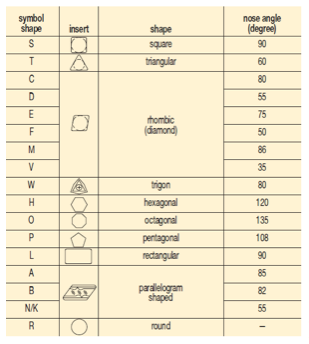
Figure 1: Kennametal Inc. Insert Shape Identification System. Image courtesy of Edmund Isakov.
![]()
2. Clearances (relief angles)
Nine relief angle values have been described in ANSI B212.12-1991 standard. These angles are the difference from 90° measured in a plane normal to the cutting edge generated by the angle between the flank and top surface of the insert. Each relief angle is denoted by a capital letter as follows:
A – 3°;
B – 5°;
C – 7°;
D – 15°;
E – 20°;
F – 25°;
G – 30°;
N – 0°;
and P – 11°.
ANSI B212.4-2002 standard added one more capital letter O, which denotes other relief angles for new designs of indexable inserts.
3. Tolerance class
There are 14 tolerance classes that control the indexability of the inserts. Each class is denoted by a capital letter. Letters for tolerances are A, B, C, D, E, F, G, H, J, K, L, M, U and N.
Tolerances on dimensions (± from nominal) are denoted by letters A, B and T. Dimension A is the nominal inscribed circle (I.C.) of the insert. Dimension T is the thickness of the insert. For pentagon, triangle and trigon shapes, dimension B is the insert height, i.e., the distance between one side and the opposite corner (Figure 2).
For all other polygons, dimension B is the distance, measured along the bisector of the rounded off corner angle and a gage roll of nominal I.C. size tangent to the two sides opposite the corner (Figure 2). For example, if a tolerance letter is H, tolerances on dimensions (± from nominal) are: 0.0005″ on dimension A, 0.0005″ on dimension B and 0.001″ on dimension T.
![]()
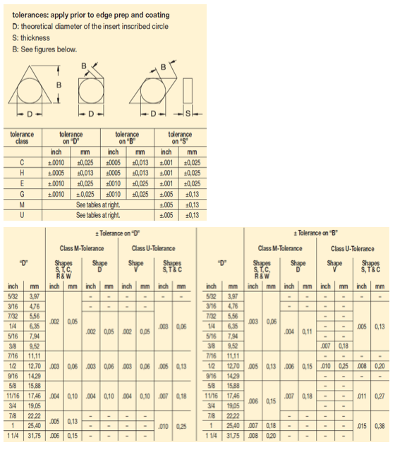
Figure 2: Kennametal Inc. Tolerance Identification System. Image courtesy of Edmund Isakov.
![]()
4. Type
The fourth position is a capital letter denoting differences in design of insert, such as the existence of fixing holes, countersinks and special features on rake surfaces. There are 15 standard types in design as follows (Figure 3):
A – With hole, without chip grooves;
B – With hole, without chip grooves, and one countersink (70°-90°);
C – With hole, without chip grooves, and two countersinks (70°-90°);
F – Without hole with chip grooves on two rake faces;
G – With hole and chip grooves on two rake faces;
H – With hole, one countersink (70°-90°) and chip groove on one rake face;
J – With hole, two countersinks (70°-90°) and chip grooves on two rake faces;
M – With hole and chip groove on one rake face;
N – Without hole, without chip grooves;
Q – With hole, without chip grooves, and two countersinks (40°-60°);
Review the print ads from this magazine to continue
This quick advertiser review unlocks the rest of the article and keeps the full-screen reader focused on the ads instead of the page chrome.


MFGAxis Discussion