Clamp Down
Clamp Down
The technology to form, press and grind indexable carbide inserts has evolved to such a high degree that the methods to effectively clamp inserts in a cutter body have struggled to keep up, but strides are being made. Some insert shapes have advanced to the point where they have a true, 100-percent, 3D geometry with almost no flat surfaces. This requires a tool-body pocket that is dynamically shaped to accommodate the optimal geometry. For example, an insert with a wavelike feature across its back requires it be seated in a pocket with a matching shape to ensure accurate fixation with high stability.
The technology to form, press and grind indexable carbide inserts has evolved to such a high degree that the methods to effectively clamp inserts in a cutter body have struggled to keep up, but strides are being made.
Some insert shapes have advanced to the point where they have a true, 100-percent, 3D geometry with almost no flat surfaces. This requires a tool-body pocket that is dynamically shaped to accommodate the optimal geometry. For example, an insert with a wavelike feature across its back requires it be seated in a pocket with a matching shape to ensure accurate fixation with high stability.


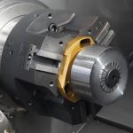
A double clamping system provides rigidity and high indexing accuracy. All images courtesy Tungaloy America.
Any insert movement will increase tool wear and degrade the surface finish even when cutting relatively soft materials. While cutting even a hard piece of cheese is no problem when the knife and cheese are held steady, the same can't be said when one is loosely held. The same principles apply when cutting metal.
Dovetail Design
To prevent an insert from rotating in a cutter pocket, a dovetail structure interfaces with the pocket and securely locks the insert on its back face. (See bottom photo on page 60.) As the cutting force hits the bottom edge of the insert, the force attempts to flip the insert. But on the top face of the insert, at the dovetail lock, is a positive stop to resist that force.
With this design, minimal clamping force is required to keep the insert in the pocket. Even if the insert's clamping screw is engaged relatively loosely, the dovetail geometry prevents the insert from becoming unclamped.
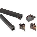
Having a clamping screw in the middle of an insert and a clamp on top of the insert performs a similar function as the dovetail lock, but the time to index an insert drastically increases. (See photos below.) This is because an end user must remove the screw, unscrew and move the clamp, index the insert, reposition the screw and then screw the clamp back into place. This time-consuming indexing activity is unacceptable in a production environment, but even at a job shop, the amount of time spent actuating an additional clamping mechanism can add up.

A continually variable, 3D rake face ensures optimal chip formation in any cutting condition.
While on the topic of screws, the condition of the screw thread significantly impacts the screw's ability to effectively clamp an insert. You can determine thread condition by noting the resistance felt during the final half to quarter turn of the screw. If that resistance isn't felt, it's definitely time to change the screw because the thread has suffered elastic deformation.
Nonetheless, it's best to change the screw each time an insert is changed. The cost of a screw is a tiny percentage of the cost of an insert and an even a smaller percentage of the cost of the cutter body, which is, ultimately, the item that will suffer most when an insert violently comes out of its pocket because of a worn screw.
A wedge clamp can be employed to eliminate the clamping screw. A wedge clamp is actuated from nearly a 45° angle, and it grips the top of an insert without going through its center bore. However, this option is only suitable when machining short-chipping materials, such as cast iron, because a wedge clamp does not provide enough space for chip evacuation when cutting longer-chipping materials, such as steel and stainless.


The V-shaped bottom provides core strength to small-diameter cutter bodies, and the increased contact area on the insert seat enhances rigidity.

The dovetail clamping system prevents insert movement and effectively "locks" when fixated.
A Tangential Strategy
Several benefits are realized by mounting an insert tangentially. For one, because the insert is not extending deeply into the core of the cutter body, the core can be thicker. Essentially, less material is removed from the body during manufacturing, so the body has a stronger base. In addition, the insert is more resistant to fracturing because the cutting force directly targets the longest and strongest piece of carbide. Instead of hammering the thinnest piece of carbide, a tangentially mounted insert twists the cutting force longitudinally along its axis, providing the strength of the full insert width behind it.
Because the insert is mounted from the side, the hole for the clamping screw is larger on a tangentially mounted insert than an insert mounted in the standard style. This is because the full width of the carbide profile is available for placement of a hole and the countersunk area for the screw head, and the larger the screw, the more robust the screw thread and the higher the clamping force. Although other types use this strategy, tangentially mounted inserts utilize it in the easiest manner.
To prevent an insert, such as one in a milling cutter, from becoming dislodged due to centrifugal force, a V shape can be ground into the bottom of the insert. (See photo above.) This provides extra clamping area in the tool body because taking a straight-line bottom and forming it into a V increases the length.

This unique clamping system Improves rigidity, according to Tungaloy.
During high-speed machining, the rotational velocity of the cutter wants to throw an insert out of its pocket. However, the V shape, with its two stable planes of contact, holds the insert in a singular area and prevents that from happening.
In small-diameter tools, the V shape provides core strength to the cutter body. The increased steel area on the insert seat also enhances rigidity.
Similar to the V-shaped bottom, a triangular insert has a long cutting edge that enhances contact with the pocket. Compared to many other insert shapes, the triangle shape also enables a larger screw to penetrate the middle of the insert. Essentially, a triangular insert provides the benefits of a positive-style rectangular insert but with more surface area to contact the pocket and a larger berth for a center screw hole and countersink.

Instead of using two screws, a large, single screw for insert fixation avoids jeopardizing the smoothness of the insert's front rake face and reducing insert integrity. The two-screw method is also problematic for production shops, because it takes twice as long to actuate the screws when changing an insert.
Effective cutter design doesn't just consider the cutting forces acting on an insert. When an insert edge is not cutting, it must be completely protected. While that might not have been considered a big deal years ago, the science of cutting has progressed to the point that chips that even lightly graze the rake face of an unused edge can significantly damage the subsequent machining performance of that edge.
When machining aluminum, researchers have determined the upper speed limit to be about 60,000 sfm (18,288 m/min.). A modern carbide grade with the proper coating could withstand such an insanely high cutting velocity, but today's technology wouldn't allow an insert to be clamped securely enough to cut aluminum at 60,000 sfm. The clamping integrity will always be the leading element in determining how far machining with indexable-insert cutting tools can go. Unless highly advanced materials are developed to make insert screws, such a high cutting speed will most likely never be achieved.

Clamping with Slanted Screws
Typically, holes for insert clamping screws are drilled and tapped at a 0° angle. With SS-FiT (Slant Screw Fixation Technology), Tungaloy cants the major diameter thread to the minor diameter hole. Therefore, when an end user engages the screw, it not only pulls the insert against its primary support on the back of the insert, but it also pulls the insert into the pocket.
This arrangement physically deforms the shape of the screw and pushes the thread flanks of the male thread into the valleys of the female thread. By physically deforming the screw, screw-thread engagement increases about 40 percent. It also prevents the threads from disengaging because of vibration, providing somewhat of a shock damper.
 is available from Tungaloy America.")
SS-FiT (Slant Screw Fixation Technology) is available from Tungaloy America.