A host of different toolholders are available, including endmill holders, milling chucks, collet chucks, hydraulic chucks and shrink-fit holders, as well as tool bodies for holding inserts to perform operations such as turning, grooving and parting off. To optimize machine tool performance, end users must consider a variety of elements, depending on the application.
One critical consideration is rigidity of the entire toolholding assembly from the machine spindle to the tool tip. The most rigid toolholder type remains the endmill holder, according to Frank Fullone, general manager of Lyndex-Nikken Inc. in Mundelein, Illinois. Unfortunately, an endmill holder is not conducive to maintaining a low total indicator runout, another key consideration.
That “old technology” design requires tightening a lock screw on a flat or Weldon shank to securely clamp the cutting tool, explained Michael Herman, vice president of sales for BIG DAISHOWA Inc. in Hoffman Estates, Illinois. Tightening the screw elliptically pushes the tool off center in the holder. “That gives 100% security for the tool not coming out, but it’s probably the worst-case scenario as far as the TIR on the tool.”
The next option is a milling chuck, Herman said, which is a mechanical chuck with needle bearings pitched at a slight angle. The runout is less than 0.01 mm (0.0004") at four times diameter.
He added that another measurement for TIR is made at the face of the collet. “Generally speaking, if you improve TIR by 0.001", you’re improving your tool life and your cost by 10%.”
For high-speed applications, the toolmaker offers Mega New Baby collet chucks, which provide excellent clamping and runout accuracy, according to Herman. The company reports that every collet is inspected twice to guarantee runout accuracy of 0.0004" at the collet nose and 0.00012" at four times diameter.
A shrink-fit holder provides a high degree of tool security, Herman noted, if the tool shank is ground to the correct H tolerance. For example, a shank that is ground undersized slightly will reduce the clamping pressure, or gripping force — another key consideration.
“Ultimately, the best choice is a hydraulic chuck,” he said, “and that is also the best because it gives you some dampening effect. It’s a very easy solution for an operator to mechanically tighten the screw, which compresses the bladder 360° around the tool itself.”
The contact between the toolholder taper and the machine spindle taper is of key importance for rigidity, Fullone said, because that is the largest surface area in contact with the spindle. “The greater the surface area that you have, of course, the greater rigidity you have.”
When high-speed machining, however, there is a tendency for the machine spindle to bell mouth, reducing the amount of contact between a steep taper holder and the spindle, Fullone explained. Also, in very rigid machining, the tool tends to bend or slightly pull out of the spindle, depending on the cutting forces. To increase the bending moment of the tool and help overcome those tendencies, Lyndex-Nikken offers dual contact holders that contact both the spindle and tool face.
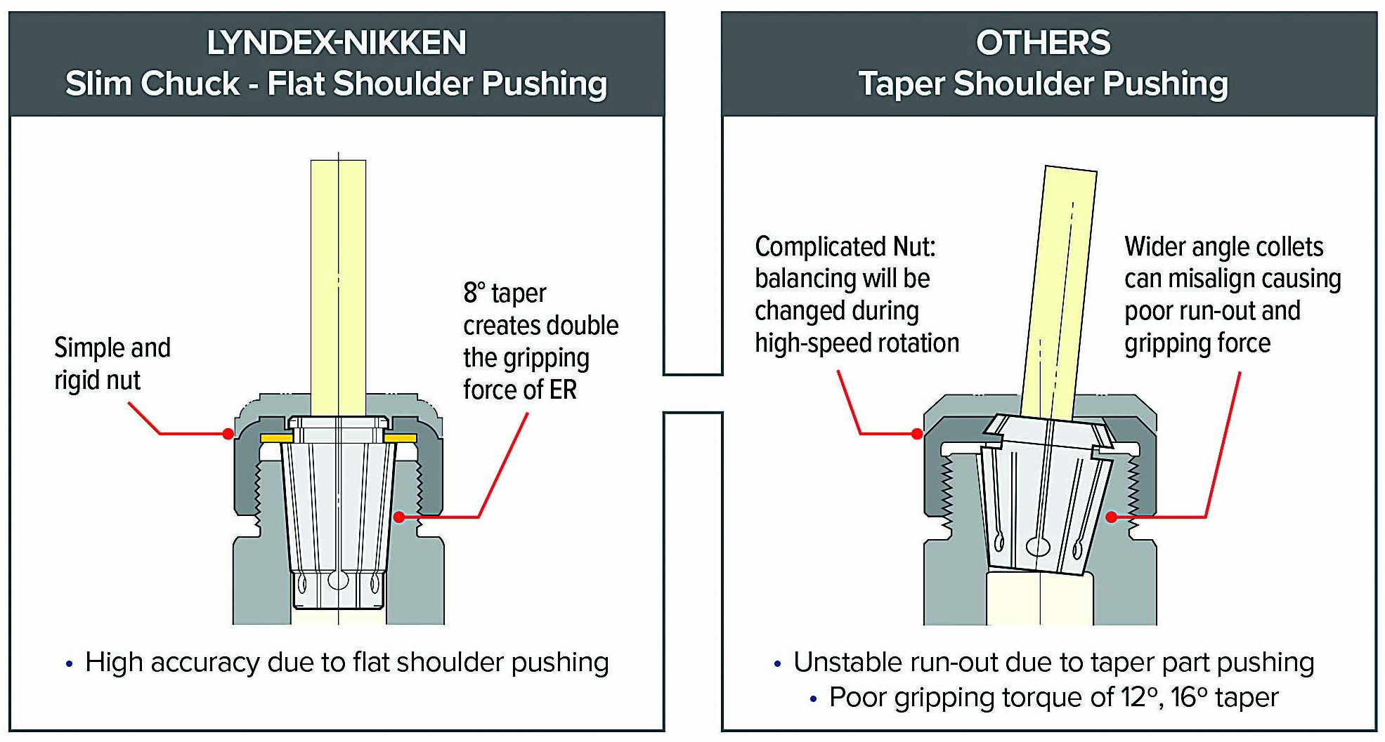
In addition, the company offers Slim Chuck SK collets, Fullone said, which has an 8° taper that reportedly doubles the gripping force of an ER collet. “The one that we find is most successful with respect to rigidity is our SK system by Nikken.”
He added that the company uses a TiN-coated bearing nut in its SK collet chucks to increase tool rigidity and toolholder accuracy by not causing the collet to become twisted or contorted as a result of the friction between the collet and nut as it is being tightened. “That TiN bearing nut does a world of wonders for concentricity and for gripping force — sometimes almost immeasurable.”
Minimizing Deflection
BIG DAISHOWA also offers a dual contact spindle system where the shank contacts the spindle taper and the spindle face simultaneously to minimize deflection and enhance machining rigidity. Called BIG-PLUS, Herman emphasized that BIG DAISHOWA originated the concept, which is licensed to a small number of other manufacturers that can meet its high standards. “Not all dual contact is the same. We hold the master gauges for BIG-PLUS, or dual contact. We always have the face and taper contact, and we never lose the Z orientation.”
Nonetheless, the more taper contact, the better the performance, Herman noted. While a taper contact of 85% to 90% is often considered ideal, too much contact can cause issues. “If you start getting to a 95% taper grind, you can basically have a lock fit and the toolholder becomes harder to release if it’s not ground properly.”
He added that there is a certain amount of micro elasticity that occurs, enabling the spindle to open slightly and accept the holder. That capability is beneficial because BIG DAISHOWA targets an AT2 angle tolerance for its holders.
Other toolholder manufacturers, such as Lyndex-Nikken, use AT3 as the standard for holders, Fullone said. “The AT2 tolerance is generally used for the angle tolerance of the spindle, because although you could achieve an AT2 tolerance on a toolholder, the problem that you have is such a tight fit that tool changing would become difficult.”
Even if a part manufacturer has high-quality toolholders, they must be properly maintained to function as designed, Herman said. For instance, an endmill should be thoroughly cleaned and dried before being inserted into any type of clamping system.
However, a tool shank can be ground to achieve an extremely fine finish and improve TIR that it slips out slightly when held in a hydraulic chuck or shrink-fit holder, Herman added. “The surface finish is so good there’s nothing to really clamp onto.”
After purchasing a new machine tool, Herman recommended, end users should consider purchasing new toolholders, especially to replace older tooling even though they have a perceived value. “Everything on that toolholder is transferred to the new spindle. You will lose accuracies from day one by using old tools that could be damaged.”
Balancing Act
A toolholder’s balance is another key consideration but some people discount it, according to Fullone. “The common comment that I’ve heard in my 30-plus years is that a balancing machine doesn’t make a chip, and they don’t understand the validity of it. It’s the same comment that’s made about presetting.”
The importance of balancing a toolholder assembly is that it increases the longevity of spindle bearings and improves a part’s surface finish by minimizing vibration, he added. To achieve a balanced assembly after spinning it in a balancing machine to locate any potential imbalance, end users remove weight such as by milling flats, add weight such as inserting screws along the flange of the toolholder or use some other method such as balancing rings.
Because a cutting tool weighs considerably less than a toolholder, which is factory balanced, Fullone conceded that inserting a tool into the holder can have minimal impact, depending on the type of tool, tool construction, number of tool components and its mass. “If it’s a ½" endmill, assuming that the holder is going to run at 15,000 or 18,000 rpm, it’s not going to affect the balance in most cases. You can’t say never, but in most cases you’re still fine with the factory balance.”
Herman noted that a holder assembly can be perfectly balanced, which might require the addition of weighted screws or milling flats to remove material, and then the balance is off once a different tool is inserted. “How much do you want to chase after that. Our tools are balanced during our manufacturing process. We use ground threads and ground nuts without flats.”
He contrasts the ISO 1940-1 balancing specification, which was developed in 1940 and is primarily considered “old school” for this reason, to ISO 16084, which was issued in 2017 and the specification that BIG DAISHOWA toolholders are balanced in accordance with. ISO 16084 focuses on the interaction between the spindle and the tool, factoring in the allowable load on the spindle bearings generated by the tool’s imbalance. This load must not exceed 1% of the dynamic load of the spindle bearings. According to ISO 16084, the allowable unbalance tolerance is specified in gmm and not the special quality grade of G.
BIG DAISHOWA does not indicate any G values for balancing quality, Herman added, but rather the maximum rotational speeds of the individual toolholder. These values are in compliance with the requirements for standard balance quality as per ISO 16084.
As the Part Turns
Because some machining operations require that the workpiece rotates while being cut by an insert held in a tool body, different considerations arise than when a rotating tool cuts a stationary workpiece. “In a part off application, we’re concerned with the balancing or the center height of the tool itself,” said Robert Navarrete, national product specialist – parting, grooving and turning for ISCAR USA in Arlington, Texas.
In parting, the goal is for the tool to be at center or above center because cylindrical forces push the insert down once it engages with the workpiece, Navarrete explained. The formula to calculate ideal center height is 0.787 mm (0.031") times insert width plus (0.0254 mm) 0.001" equals the maximum height above center. When an insert is below center, edge strength is lost. If the cutting edge is 0.254 mm (0.010") below center, a 17% loss in edge strength results.
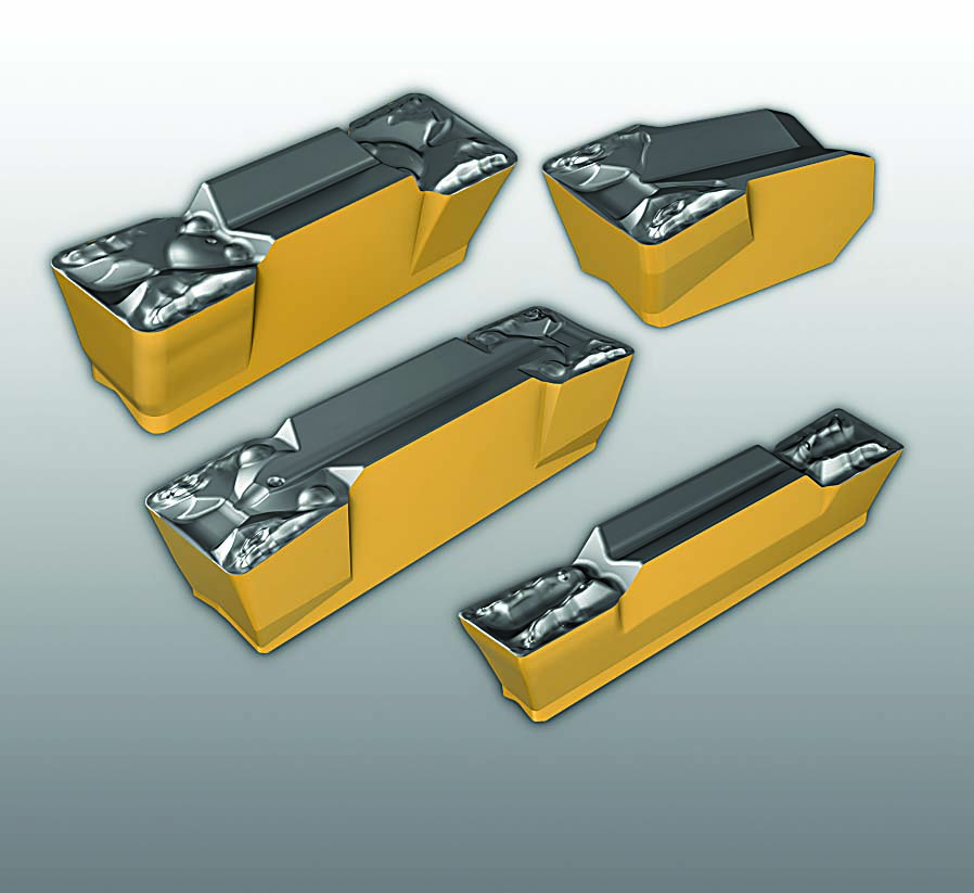
Similar to other machining applications, a rigid holder setup is important for success, enabling a straight cut, a fine surface finish and increased productivity by either boosting the feed rate or the cutting speed, Navarrete noted. To help end users achieve that, ISCAR offers the LOGIQ-F-GRIP system for parting and grooving, which has a reinforced block that enhances support from the bottom and back and effectively distributes cutting forces.
He added that LOGIQ-F-GRIP is a bulkier holder but is available in common square shank sizes that will plug into a standard tool station. “This is still a plug-and-play toolholder that will fit into any machine.”
The way the insert pocket is designed uses rotational forces to push the insert into the pocket rather than lifting it out, Navarrete explained. The design also ensures consistent pocket wear over a long period of time. In contrast to the company’s original jaw-style clamp to secure an insert, the new design does not cause the insert to bounce at a microscopic level, leading to premature wear and preventing full insert contact.
In a test that compared the original-style pocket to the LOGIQ-F-GRIP’s pocket, he said the original version completed 3,000 interrupted cuts before the pocket was worn while the LOGIQ-F-GRIP completed 7,000 interrupted cuts and the pocket appeared barely used. “So, we stopped at 7,000 because we proved our point.”
Navarrete emphasized the importance of paying attention to the wear pattern of the pocket because it is challenging to predict pocket life on the number of parts as it depends on the machining environment and metal being cut. The LOGIQ-F-GRIP’s quad blade, or adapter, has four pockets. “You’re going to be able to rotate that adapter four times. You buy one adapter; you’re getting four ends.”
Contact Details

Contact Details

Contact Details
Related Glossary Terms
- chuck
chuck
Workholding device that affixes to a mill, lathe or drill-press spindle. It holds a tool or workpiece by one end, allowing it to be rotated. May also be fitted to the machine table to hold a workpiece. Two or more adjustable jaws actually hold the tool or part. May be actuated manually, pneumatically, hydraulically or electrically. See collet.
- collet
collet
Flexible-sided device that secures a tool or workpiece. Similar in function to a chuck, but can accommodate only a narrow size range. Typically provides greater gripping force and precision than a chuck. See chuck.
- cutting speed
cutting speed
Tangential velocity on the surface of the tool or workpiece at the cutting interface. The formula for cutting speed (sfm) is tool diameter 5 0.26 5 spindle speed (rpm). The formula for feed per tooth (fpt) is table feed (ipm)/number of flutes/spindle speed (rpm). The formula for spindle speed (rpm) is cutting speed (sfm) 5 3.82/tool diameter. The formula for table feed (ipm) is feed per tooth (ftp) 5 number of tool flutes 5 spindle speed (rpm).
- endmill
endmill
Milling cutter held by its shank that cuts on its periphery and, if so configured, on its free end. Takes a variety of shapes (single- and double-end, roughing, ballnose and cup-end) and sizes (stub, medium, long and extra-long). Also comes with differing numbers of flutes.
- feed
feed
Rate of change of position of the tool as a whole, relative to the workpiece while cutting.
- flat ( screw flat)
flat ( screw flat)
Flat surface machined into the shank of a cutting tool for enhanced holding of the tool.
- gang cutting ( milling)
gang cutting ( milling)
Machining with several cutters mounted on a single arbor, generally for simultaneous cutting.
- grooving
grooving
Machining grooves and shallow channels. Example: grooving ball-bearing raceways. Typically performed by tools that are capable of light cuts at high feed rates. Imparts high-quality finish.
- milling
milling
Machining operation in which metal or other material is removed by applying power to a rotating cutter. In vertical milling, the cutting tool is mounted vertically on the spindle. In horizontal milling, the cutting tool is mounted horizontally, either directly on the spindle or on an arbor. Horizontal milling is further broken down into conventional milling, where the cutter rotates opposite the direction of feed, or “up” into the workpiece; and climb milling, where the cutter rotates in the direction of feed, or “down” into the workpiece. Milling operations include plane or surface milling, endmilling, facemilling, angle milling, form milling and profiling.
- parting
parting
When used in lathe or screw-machine operations, this process separates a completed part from chuck-held or collet-fed stock by means of a very narrow, flat-end cutting, or parting, tool.
- shank
shank
Main body of a tool; the portion of a drill or similar end-held tool that fits into a collet, chuck or similar mounting device.
- titanium nitride ( TiN)
titanium nitride ( TiN)
Added to titanium-carbide tooling to permit machining of hard metals at high speeds. Also used as a tool coating. See coated tools.
- tolerance
tolerance
Minimum and maximum amount a workpiece dimension is allowed to vary from a set standard and still be acceptable.
- toolholder
toolholder
Secures a cutting tool during a machining operation. Basic types include block, cartridge, chuck, collet, fixed, modular, quick-change and rotating.
- total indicator runout ( TIR)
total indicator runout ( TIR)
Combined variations of all dimensions of a workpiece, measured with an indicator, determined by rotating the part 360°.
- total indicator runout ( TIR)2
total indicator runout ( TIR)
Combined variations of all dimensions of a workpiece, measured with an indicator, determined by rotating the part 360°.
- turning
turning
Workpiece is held in a chuck, mounted on a face plate or secured between centers and rotated while a cutting tool, normally a single-point tool, is fed into it along its periphery or across its end or face. Takes the form of straight turning (cutting along the periphery of the workpiece); taper turning (creating a taper); step turning (turning different-size diameters on the same work); chamfering (beveling an edge or shoulder); facing (cutting on an end); turning threads (usually external but can be internal); roughing (high-volume metal removal); and finishing (final light cuts). Performed on lathes, turning centers, chucking machines, automatic screw machines and similar machines.
Author

Alan Richter, a 40-year veteran journalist, has spent the last 25 years covering the metalworking industry for Cutting Tool Engineering and currently serves as its editor-at-large. Contact him at [email protected].
Contributors
BIG DAISHOWA Inc.
888-866-5776
www.bigdaishowa.com
ISCAR USA
817-258-3200
www.iscarusa.com
Lyndex-Nikken Inc.
847-367-4800
www.lyndexnikken.com
