In parting, or cut-off, operations, the objective is to efficiently and securely separate one part of the workpiece from the other. To achieve this, a straight cut is made to a depth that equals the radius of a bar, or workpiece.
In grooving operations, the principle is the same but the cut is shallower. Therefore, the cut is not taken to the center of the workpiece. The requirements focus on groove shape, accuracy and surface finish.
All images courtesy Sandvik Coromant
These machining operations can be compared to a facing operation when turning, where the cutting tool is fed radially into the center of the workpiece. The difference when parting is that the tool is a thin blade capable of making a narrow groove. Because workpiece material is on both sides of the tool, the amount of material to be cut through should be as little as possible to reduce cutting forces and deflection of thin-wall or small-diameter components.
In addition, the width of the cutting edge should be small to minimize workpiece material consumption, which is particularly beneficial when cutting expensive material, such as Inconel or titanium. For example, an end user saves 80 ' of material annually when parting 1,000 parts a week by applying an insert with a width 0.020 " less than a comparable one (0.020 " × 1,000 parts/week × 48 workweeks per year = 960 " ÷ 12 = 80 '). This places considerable demands on the performance, chip-forming ability and stability of the parting tool.
Down to Zero
If the machine tool’s spindle speed remains constant as the parting tool moves to the center of the workpiece, the cutting speed will gradually decrease until it reaches zero at the center. A decrease in cutting speed is disadvantageous for the tool and can severely stress the cutting edge. As the edge approaches the center, pressure increases as the tool is fed at the decreasing cutting speed. In CNC lathes, the control increases the spindle speed as the tool moves toward the center to maintain the same cutting speed. Eventually, however, the machine cannot go any faster and the cutting speed decreases as the tool gets close to the center of the workpiece.
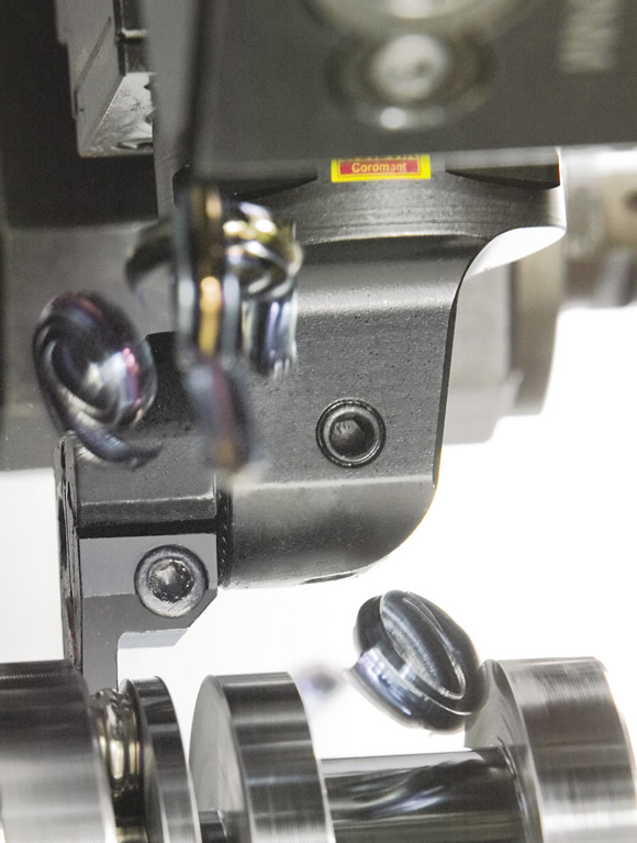
In addition, chip evacuation is critical when parting. There is little opportunity to break chips in the confined space of the cut as the tool moves deeper into the workpiece. The chipformer geometry of the cutting edge is largely devoted to forming chips so they can be smoothly evacuated. The consequences of poor evacuation are chip obstruction, which leads to poor surface quality, and chip jamming, which leads to tool breakage.
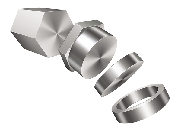
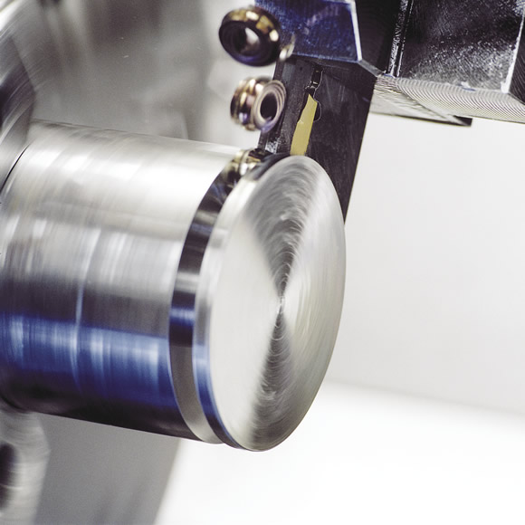
A cutoff operation is suitable for removing various portions of a workpiece.
In addition to being productive, indexable-insert parting and grooving tools are versatile. Users can perform most types of turning operations with these tools. Generally, operations that do not require the large overhang offered by an adjustable blade-type tool should be performed with a shank-type or Coromant Capto tool, where the blade is an integral part of the toolholder. This design maximizes rigidity, which is vital when parting and grooving, as well as when profiling and turning. However, an adjustable blade-type tool offers the flexibility of having an adjustable overhang for machining different workpiece diameters and deep groove depths.
Generally, minimize tool deflection and vibration by choosing:
- a toolholder or blade with the smallest overhang,
- the largest possible shank dimensions on a toolholder,
- a blade or toolholder with the largest possible insert seat (width),
- a blade height that’s at least equal to the insertion length, or DOC, and
- a reinforced blade, which enhances stability and sometimes provides deeper cutting capabilities.
For flexible overhangs, the first tool choice for parting should be tool blocks with blades, where the blade can be adjusted to optimize the tool reach and tool overhang. Screw clamp-type insert clamping is the best choice for stability, and a reinforced toolholder will further increase stability. The tool overhang should not exceed eight times the insert width, although Sandvik Coromant plans to soon offer some that exceed this rule and still cut effectively.
Entering the Cut
Different entry angles (φr) provide different benefits. There are three types: neutral, where the cutting edge is at right angles to the feed direction of the tool with an entry angle of 0°, and right- and left-hand inserts, with each having an entry angle in various degrees. Inserts with an entry angle of 5° are available in CF, CM and CR geometries. Inserts with 10° and 15° entry angles are available in the CS geometry.
The neutral insert provides a strong cutting edge, with the cutting forces being mainly radial. This provides a stable cutting action, effective chip formation and long tool life.
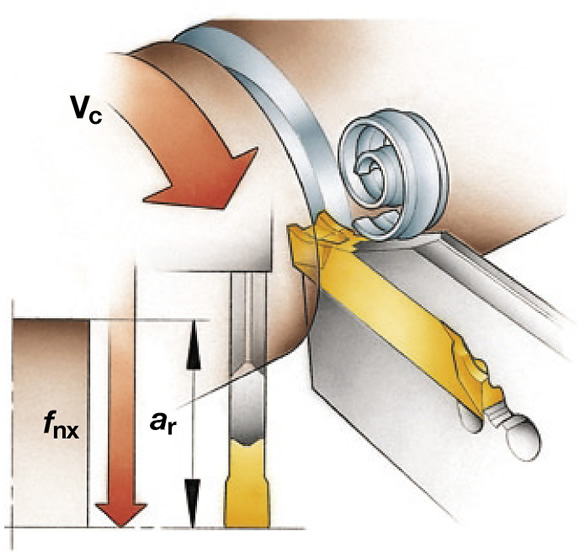
The main cutting data and tool definitions when parting and grooving are: a) Cutting speed (vc) is the surface speed at the cutting edge; b) Spindle speed (n) is measured in rpm; c) Straight, radial feed toward the center of the workpiece (fnx), and d) Radial DOC capability of the tool (ar) is the distance from the OD to the center, or bottom, of the groove when parting.
However, an entry angle is useful when parting because the end of the cut can be finished more advantageously. If a neutral insert is applied, the portion of the workpiece that a part has been cut off from is left with a small-diameter protrusion, or pip. A parting tool with an entry angle can remove the pip when the cut part drops.
The hand (left or right) of an insert is selected so the leading corner of the cutting edge is next to the part being cut off. Whether it’s a left- or right-hand tool depends on whether the user wants the pip to be on the piece being cut off or on the workpiece that remains in the machine. Applying an insert with an entry angle will also reduce burrs on tubes.
To help avoid or minimize pips and burrs, use a sharp, right- or left-hand insert, such as CS, CF, CM or CR, with the smallest possible entry angle. In addition, a neutral GF geometry, which is a grooving geometry with a sharp, ground edge, works well and is available with different corner radii. Although a larger angle is more effective for reducing pips and burrs, it tends to cut unevenly, impart a less-than-optimal surface finish and shorten tool life.
Pip size is also impacted by how the part that is cut off breaks away because of centrifugal forces. On large-diameter parts, as the spindle speed increases and there is less material to cut, centrifugal forces can throw off the portion of the workpiece being parted, depending on the spindle speed and part weight.
Pip size can also be minimized by supporting the part of the workpiece being cut off, which becomes more unstable as the operation proceeds. For best results, select inserts designed for parting operations.
To minimize tool deflection and vibration, choose a blade with the smallest overhang.
For large depth of penetration during a parting operation, a double-ended blade is recommended.
For parting small-diameter bars or workpieces and parting thin-walled tubes, cutting forces should be minimized by selecting small insert widths and sharp cutting edges, such as CS, CF and GF geometries. The choice of insert width is a compromise between tool strength and stability on the one hand and minimizing workpiece material consumption and lowering cutting forces on the other. CTE
Related Glossary Terms
- computer numerical control ( CNC)
computer numerical control ( CNC)
Microprocessor-based controller dedicated to a machine tool that permits the creation or modification of parts. Programmed numerical control activates the machine’s servos and spindle drives and controls the various machining operations. See DNC, direct numerical control; NC, numerical control.
- cutoff
cutoff
Step that prepares a slug, blank or other workpiece for machining or other processing by separating it from the original stock. Performed on lathes, chucking machines, automatic screw machines and other turning machines. Also performed on milling machines, machining centers with slitting saws and sawing machines with cold (circular) saws, hacksaws, bandsaws or abrasive cutoff saws. See saw, sawing machine; turning.
- cutting speed
cutting speed
Tangential velocity on the surface of the tool or workpiece at the cutting interface. The formula for cutting speed (sfm) is tool diameter 5 0.26 5 spindle speed (rpm). The formula for feed per tooth (fpt) is table feed (ipm)/number of flutes/spindle speed (rpm). The formula for spindle speed (rpm) is cutting speed (sfm) 5 3.82/tool diameter. The formula for table feed (ipm) is feed per tooth (ftp) 5 number of tool flutes 5 spindle speed (rpm).
- feed
feed
Rate of change of position of the tool as a whole, relative to the workpiece while cutting.
- grooving
grooving
Machining grooves and shallow channels. Example: grooving ball-bearing raceways. Typically performed by tools that are capable of light cuts at high feed rates. Imparts high-quality finish.
- outer diameter ( OD)
outer diameter ( OD)
Dimension that defines the exterior diameter of a cylindrical or round part. See ID, inner diameter.
- parting
parting
When used in lathe or screw-machine operations, this process separates a completed part from chuck-held or collet-fed stock by means of a very narrow, flat-end cutting, or parting, tool.
- shank
shank
Main body of a tool; the portion of a drill or similar end-held tool that fits into a collet, chuck or similar mounting device.
- toolholder
toolholder
Secures a cutting tool during a machining operation. Basic types include block, cartridge, chuck, collet, fixed, modular, quick-change and rotating.
- turning
turning
Workpiece is held in a chuck, mounted on a face plate or secured between centers and rotated while a cutting tool, normally a single-point tool, is fed into it along its periphery or across its end or face. Takes the form of straight turning (cutting along the periphery of the workpiece); taper turning (creating a taper); step turning (turning different-size diameters on the same work); chamfering (beveling an edge or shoulder); facing (cutting on an end); turning threads (usually external but can be internal); roughing (high-volume metal removal); and finishing (final light cuts). Performed on lathes, turning centers, chucking machines, automatic screw machines and similar machines.