Cutting external threads is one of the more difficult machining operations. Achieving the proper thread form can be challenging, and tool chipping and premature tool wear are often problematic because of insufficient surface speeds and high cutting pressures.
Nevertheless, there are many ways to successfully cut external threads, including chasing them with a die, single-point turning, whirling, rolling and milling. However, the worst aspect of machining a threaded part usually isn’t making the thread, but gripping the part afterwards for doing a secondary operation.
Consider turning a knurled-head, socket head cap screw having dimensions of 1⁄2-13×2”. A shop with a 2-axis CNC lathe would most likely load bar stock at least 9⁄16” in diameter into the feeder, face, chamfer and turn the major diameter and screw head, knurl it, cut the thread and part off. All that’s left is to face, drill and broach the opposite end.

A split sleeve can be an effective method for gripping threaded parts.
But how do you grab the thing without damaging the threads?
For many machinists, their first inclination is to use the thread flanks and pitch diameter as the locating surface. One way to do this is by wrapping the thread with a length of copper wire, large enough in diameter so the collet or chuck touches the copper rather than the thread’s major diameter. For low volumes and prototypes, this is a simple and cost-effective workholding method. The downside is the time-consuming wrapping and subsequent unwrapping of the bolt. Unless a machinist uses high-quality wire and carefully wraps the thread, concentricity between the first and second operations may suffer. This is not a big deal for a socket head cap screw, but many threaded parts require greater accuracy.
A similar approach is to thread a pair of nuts with a lock washer between them up to the head of the bolt and use a third nut near the opposite end to steady the assembly when placing it into a 3-jaw chuck or hex-shaped collet. This effectively grips the workpiece, but—as with the copper wire—success depends on the accuracy of the clamping nuts, and spinning the nuts on and off the workpiece is tedious at best.
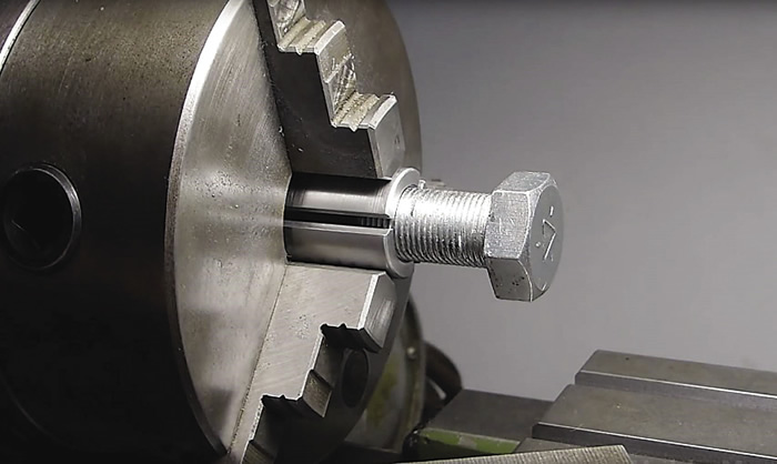
Taken one step further, a threaded bushing can be made by drilling and tapping a 1⁄2-13 hole in tool steel—or another durable material—that’s roughly twice the diameter of the thread, then slicing this ad hoc fixture into pie-shaped pieces. Clean the threads carefully to remove any burrs, place the pieces around the workpiece and locate the captured workpiece in the lathe chuck.
As with most parts, how the thread is gripped depends on what it will be used for. A 1018 steel fastener for a tractor engine, for example, has far less stringent requirements than one used to retain the landing gear on a fighter jet. Some companies might frown on engaging the threads of an aircraft or medical part in this manner, so it’s important to check with the customer for form, fit and finish requirements. Always watch for scuff marks or other cosmetic damage when clamping on the thread flanks and pitch diameter, as previously described.
What material the bolt is made of also plays a huge factor in how it is clamped. Speaking from years of making threaded parts from difficult-to-machine materials, such as Inconel and stainless steel, many of which had tight form and diameter tolerances, one of the best approaches is to simply clamp on the OD with a hardened steel collet. This reduces the major diameter by a few tenths, but I never had any problems meeting print dimensions or holding concentricity in this manner. And, part slippage was not a concern, provided the clamping pressure applied was 30 psi or higher (the actual pressure applied depended on the workpiece size and configuration).
That said, this didn’t work for me on aluminum or copper parts—the collet smashed the heck out of the thread crests. Nor did I have much luck with pie jaws or “emergency” collets. These are made of steel, aluminum or iron, which are soft enough to be machined to fit the workpiece and, at first glance, would seem a logical choice for this application. Their softness is their downfall, however, as the ID of the bored emergency collet or soft jaw was soon lined with grooves and creases from the part’s thread peaks. Also, concentricity became an issue.
Related Glossary Terms
- broach
broach
Tapered tool, with a series of teeth of increasing length, that is pushed or pulled into a workpiece, successively removing small amounts of metal to enlarge a hole, slot or other opening to final size.
- bushing
bushing
Cylindrical sleeve, typically made from high-grade tool steel, inserted into a jig fixture to guide cutting tools. There are three main types: renewable, used in liners that in turn are installed in the jig; press-fit, installed directly in the jig for short production runs; and liner (or master), installed permanently in a jig to receive renewable bushing.
- chuck
chuck
Workholding device that affixes to a mill, lathe or drill-press spindle. It holds a tool or workpiece by one end, allowing it to be rotated. May also be fitted to the machine table to hold a workpiece. Two or more adjustable jaws actually hold the tool or part. May be actuated manually, pneumatically, hydraulically or electrically. See collet.
- collet
collet
Flexible-sided device that secures a tool or workpiece. Similar in function to a chuck, but can accommodate only a narrow size range. Typically provides greater gripping force and precision than a chuck. See chuck.
- computer numerical control ( CNC)
computer numerical control ( CNC)
Microprocessor-based controller dedicated to a machine tool that permits the creation or modification of parts. Programmed numerical control activates the machine’s servos and spindle drives and controls the various machining operations. See DNC, direct numerical control; NC, numerical control.
- fixture
fixture
Device, often made in-house, that holds a specific workpiece. See jig; modular fixturing.
- gang cutting ( milling)
gang cutting ( milling)
Machining with several cutters mounted on a single arbor, generally for simultaneous cutting.
- inner diameter ( ID)
inner diameter ( ID)
Dimension that defines the inside diameter of a cavity or hole. See OD, outer diameter.
- lathe
lathe
Turning machine capable of sawing, milling, grinding, gear-cutting, drilling, reaming, boring, threading, facing, chamfering, grooving, knurling, spinning, parting, necking, taper-cutting, and cam- and eccentric-cutting, as well as step- and straight-turning. Comes in a variety of forms, ranging from manual to semiautomatic to fully automatic, with major types being engine lathes, turning and contouring lathes, turret lathes and numerical-control lathes. The engine lathe consists of a headstock and spindle, tailstock, bed, carriage (complete with apron) and cross slides. Features include gear- (speed) and feed-selector levers, toolpost, compound rest, lead screw and reversing lead screw, threading dial and rapid-traverse lever. Special lathe types include through-the-spindle, camshaft and crankshaft, brake drum and rotor, spinning and gun-barrel machines. Toolroom and bench lathes are used for precision work; the former for tool-and-die work and similar tasks, the latter for small workpieces (instruments, watches), normally without a power feed. Models are typically designated according to their “swing,” or the largest-diameter workpiece that can be rotated; bed length, or the distance between centers; and horsepower generated. See turning machine.
- milling
milling
Machining operation in which metal or other material is removed by applying power to a rotating cutter. In vertical milling, the cutting tool is mounted vertically on the spindle. In horizontal milling, the cutting tool is mounted horizontally, either directly on the spindle or on an arbor. Horizontal milling is further broken down into conventional milling, where the cutter rotates opposite the direction of feed, or “up” into the workpiece; and climb milling, where the cutter rotates in the direction of feed, or “down” into the workpiece. Milling operations include plane or surface milling, endmilling, facemilling, angle milling, form milling and profiling.
- outer diameter ( OD)
outer diameter ( OD)
Dimension that defines the exterior diameter of a cylindrical or round part. See ID, inner diameter.
- pitch
pitch
1. On a saw blade, the number of teeth per inch. 2. In threading, the number of threads per inch.
- tapping
tapping
Machining operation in which a tap, with teeth on its periphery, cuts internal threads in a predrilled hole having a smaller diameter than the tap diameter. Threads are formed by a combined rotary and axial-relative motion between tap and workpiece. See tap.
- turning
turning
Workpiece is held in a chuck, mounted on a face plate or secured between centers and rotated while a cutting tool, normally a single-point tool, is fed into it along its periphery or across its end or face. Takes the form of straight turning (cutting along the periphery of the workpiece); taper turning (creating a taper); step turning (turning different-size diameters on the same work); chamfering (beveling an edge or shoulder); facing (cutting on an end); turning threads (usually external but can be internal); roughing (high-volume metal removal); and finishing (final light cuts). Performed on lathes, turning centers, chucking machines, automatic screw machines and similar machines.
Author

Kip Hanson is a contributing editor for Cutting Tool Engineering magazine. Contact him by phone at (520) 548-7328 or via e-mail at [email protected].
