In challenging economic times, part manufacturers typically are loath to outsource a job to a competitor when there’s a way to do it in-house. Akron (Ohio) Gear & Engineering Inc. faced this situation a year ago when COVID-19 significantly reduced the workload at the company. It specializes in machining large parts, including industrial gears, and didn’t want to pass on a project to make a 0.9 metric ton (1 ton) ring made of 4340 steel even though the most appropriate machine for the job was being rebuilt, said Akron Gear & Engineering’s Dennis Miller.
“The expense of the whole job was more than if we would have farmed it out,” he said, noting the high cost for required tooling. “But if we weren’t able to do (it), we may have lost their business. We didn’t want to take a gamble.”
With its largest vertical turret lathe, which has a 3,098.8 mm (122") capacity, unavailable at the time, Akron Gear & Engineering needed to machine the ring on its Juaristi horizontal CNC boring mill but didn’t have the necessary fixturing. Using the boring mill instead of the VTL required the ring to be held vertically rather than horizontally. The boring mill with 3+2 capability has capacities of 2,997.2 mm (118") on the x-axis, 2,413 mm (95") on the y-axis and 711.2 mm (28") on the spindle.
Miller contacted a familiar workholding supplier for a solution but never heard back. Unwilling to wait any longer, he called industrial distributor Atwood Industries Inc. in Cleveland, which recommended workholding from Mitee-Bite Products LLC in Center Ossipee, New Hampshire. After discussing the job with Michael Witzgall, senior applications manager at Mitee-Bite Products, a modular arrangement mounted on T-slot subplates was recommended. The workholding devices included Mitee-Bite Products’ Heavy Duty T-slot clamps with blunt-edge Pitbull clamps and large multifixture stops for the first operation, then modular XYZ Xpansion pins for ID, OD and facing operations.
“The modular design was vital with this application to avoid distortion from clamping pressure,” said David Bishop, general manager of Mitee-Bite Products. “Large, one-piece runs leave very little room for error. Preventing distortion with this heavy, ring-shaped part required solid communication with the customer, an extensive brainstorming session and CAD simulation software to recommend the best options. Mounting the T-slot plates centered on the ring’s diameter allows placement of all clamps and hard stops into a static position and then applying contact pressure in small increments equally in all directions until sufficient holding force was achieved.”
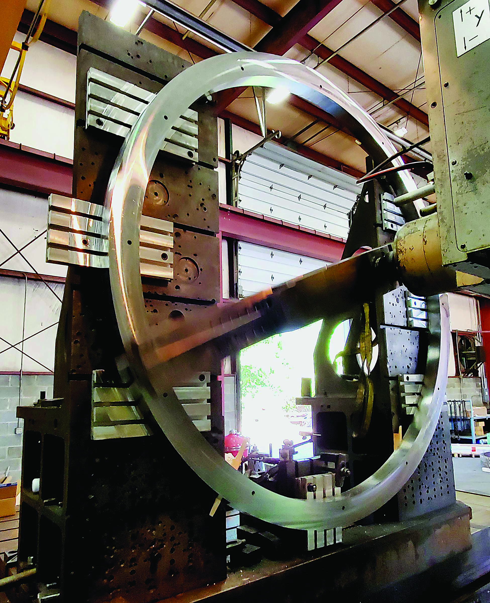
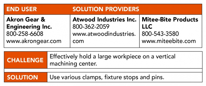
A 0.9 metric ton ring is bored at Akron Gear & Engineering. Image courtesy of Mitee-Bite Products
Lacking experience with goods from Mitee-Bite Products, Miller worried whether its workholders would be up to the task of holding the massive part.
“If the clamps or pins fail,” he said, “it’s coming down on me. You have to put your faith and trust into the salesman who is selling them to you, hoping he is not exaggerating on the quality of his parts.”
Bishop estimated that it would take more than 4,536 kg (10,000 lbs.) of force to shear an XYZ Xpansion pin, which is made of 17-4 PH stainless steel.
“We were not concerned about any lack of strength in the x, y and z directions,” he said.
Miller said the OD of the ring measures 2,247.9 mm (88.5"), the ID is 1,993.9 mm (78.5") and the thickness is 107.95 mm (4.25"). As it turned out, the part was taller than Akron Gear & Engineering’s angle plates, preventing the top section from being clamped.
“It took a lot longer than what was expected because machining the unclamped area on the top produced a lot of vibration,” he said, adding that the ring took about a week to machine on the vertical turning center. “If we did it on the larger VTL, we could have done the entire job in two days.”
Miller began the work by applying a 152.4 mm (6") facemill to cover the entire face in one pass. Adding to his concerns about vibration and chatter, the crust of the workpiece material was harder than the subsurface.
“I switched to a 4" (101.6 mm) facemill to get through the surface,” he said. “Once below the crust, I was able to go back to (a) 6" mill.”
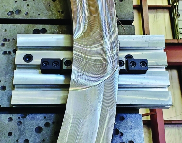
A detail is displayed of Mitee-Bite Products’ fixturing that Akron Gear
& Engineering used to hold a 0.9 metric ton ring. Image courtesy of Mitee-Bite Products
Miller said the larger facemill ran at a 1.524 mm (0.06") DOC and a 2,286 mm/min. (90 ipm) feed rate to help minimize vibration. A 1.83 m (6') boring bar from Allied Machine & Engineering Corp. with a single-point insert was used to finish the OD and ID, taking from 0.508 to 0.762 mm (0.02" to 0.03") DOC per pass to remove the remaining 3.175 mm (0.125") of material on both features.
He said the T-slot subplates were machined flat with a recess on both the ID and OD so that when the boring bar cleared the edge, the bar would not contact the subplates. They were bolted or clamped onto the angle plates, and the Pitbull clamps held the part in the first set.
“With this setup, I was able to mill and finish one face and drill and ream the holes in the part,” Miller said. “Once this operation was done, the ring was removed and holes were drilled and tapped into the subplates for the Xpansion pins. Once the pins were tightened down, I started the second side by milling the face and then circle milling the ID and OD to 0.125" from finish size.”
He said the XYZ Xpansion pins leave the part free from clamp interference.
“We can do three sides in one setup,” Miller said, “saving a load of setup time from moving clamps and indicating the bore countless times. Just goes to show you that you don’t need the biggest clamp to hold the bigger parts.”
After completing the job, he asked the sales representative at the initial supplier that Akron Gear & Engineering had considered why the sales rep never replied.
“He blamed it on COVID-19,” Miller said.
“What really impressed me was how quickly (Akron Gear & Engineering) put the plan in action,” Bishop said. “As the old saying goes, if you’re not making chips, you’re not making money.”
Contact Details

Related Glossary Terms
- boring
boring
Enlarging a hole that already has been drilled or cored. Generally, it is an operation of truing the previously drilled hole with a single-point, lathe-type tool. Boring is essentially internal turning, in that usually a single-point cutting tool forms the internal shape. Some tools are available with two cutting edges to balance cutting forces.
- boring bar
boring bar
Essentially a cantilever beam that holds one or more cutting tools in position during a boring operation. Can be held stationary and moved axially while the workpiece revolves around it, or revolved and moved axially while the workpiece is held stationary, or a combination of these actions. Installed on milling, drilling and boring machines, as well as lathes and machining centers.
- chatter
chatter
Condition of vibration involving the machine, workpiece and cutting tool. Once this condition arises, it is often self-sustaining until the problem is corrected. Chatter can be identified when lines or grooves appear at regular intervals in the workpiece. These lines or grooves are caused by the teeth of the cutter as they vibrate in and out of the workpiece and their spacing depends on the frequency of vibration.
- computer numerical control ( CNC)
computer numerical control ( CNC)
Microprocessor-based controller dedicated to a machine tool that permits the creation or modification of parts. Programmed numerical control activates the machine’s servos and spindle drives and controls the various machining operations. See DNC, direct numerical control; NC, numerical control.
- computer-aided design ( CAD)
computer-aided design ( CAD)
Product-design functions performed with the help of computers and special software.
- facemill
facemill
Milling cutter for cutting flat surfaces.
- feed
feed
Rate of change of position of the tool as a whole, relative to the workpiece while cutting.
- flat ( screw flat)
flat ( screw flat)
Flat surface machined into the shank of a cutting tool for enhanced holding of the tool.
- gang cutting ( milling)
gang cutting ( milling)
Machining with several cutters mounted on a single arbor, generally for simultaneous cutting.
- inner diameter ( ID)
inner diameter ( ID)
Dimension that defines the inside diameter of a cavity or hole. See OD, outer diameter.
- lathe
lathe
Turning machine capable of sawing, milling, grinding, gear-cutting, drilling, reaming, boring, threading, facing, chamfering, grooving, knurling, spinning, parting, necking, taper-cutting, and cam- and eccentric-cutting, as well as step- and straight-turning. Comes in a variety of forms, ranging from manual to semiautomatic to fully automatic, with major types being engine lathes, turning and contouring lathes, turret lathes and numerical-control lathes. The engine lathe consists of a headstock and spindle, tailstock, bed, carriage (complete with apron) and cross slides. Features include gear- (speed) and feed-selector levers, toolpost, compound rest, lead screw and reversing lead screw, threading dial and rapid-traverse lever. Special lathe types include through-the-spindle, camshaft and crankshaft, brake drum and rotor, spinning and gun-barrel machines. Toolroom and bench lathes are used for precision work; the former for tool-and-die work and similar tasks, the latter for small workpieces (instruments, watches), normally without a power feed. Models are typically designated according to their “swing,” or the largest-diameter workpiece that can be rotated; bed length, or the distance between centers; and horsepower generated. See turning machine.
- milling
milling
Machining operation in which metal or other material is removed by applying power to a rotating cutter. In vertical milling, the cutting tool is mounted vertically on the spindle. In horizontal milling, the cutting tool is mounted horizontally, either directly on the spindle or on an arbor. Horizontal milling is further broken down into conventional milling, where the cutter rotates opposite the direction of feed, or “up” into the workpiece; and climb milling, where the cutter rotates in the direction of feed, or “down” into the workpiece. Milling operations include plane or surface milling, endmilling, facemilling, angle milling, form milling and profiling.
- milling machine ( mill)
milling machine ( mill)
Runs endmills and arbor-mounted milling cutters. Features include a head with a spindle that drives the cutters; a column, knee and table that provide motion in the three Cartesian axes; and a base that supports the components and houses the cutting-fluid pump and reservoir. The work is mounted on the table and fed into the rotating cutter or endmill to accomplish the milling steps; vertical milling machines also feed endmills into the work by means of a spindle-mounted quill. Models range from small manual machines to big bed-type and duplex mills. All take one of three basic forms: vertical, horizontal or convertible horizontal/vertical. Vertical machines may be knee-type (the table is mounted on a knee that can be elevated) or bed-type (the table is securely supported and only moves horizontally). In general, horizontal machines are bigger and more powerful, while vertical machines are lighter but more versatile and easier to set up and operate.
- modular design ( modular construction)
modular design ( modular construction)
Manufacturing of a product in subassemblies that permits fast and simple replacement of defective assemblies and tailoring of the product for different purposes. See interchangeable parts.
- outer diameter ( OD)
outer diameter ( OD)
Dimension that defines the exterior diameter of a cylindrical or round part. See ID, inner diameter.
- payload ( workload)
payload ( workload)
Maximum load that the robot can handle safely.
- turning
turning
Workpiece is held in a chuck, mounted on a face plate or secured between centers and rotated while a cutting tool, normally a single-point tool, is fed into it along its periphery or across its end or face. Takes the form of straight turning (cutting along the periphery of the workpiece); taper turning (creating a taper); step turning (turning different-size diameters on the same work); chamfering (beveling an edge or shoulder); facing (cutting on an end); turning threads (usually external but can be internal); roughing (high-volume metal removal); and finishing (final light cuts). Performed on lathes, turning centers, chucking machines, automatic screw machines and similar machines.
- turret lathe
turret lathe
Differs from engine lathe in that the normal compound rest is replaced by pivoting, multitool turrets mounted on the cross slide and tailstock. See lathe.
Author
News items authored by Cutting Tool Engineering have been written or edited by the editors of Cutting Tool Engineering magazine. The reports represent material submitted to CTE by outside authors, and edited by CTE editors for style and accuracy.
