There are numerous advantages to rigidly holding a workpiece: feed rates can be increased and cutting times reduced, cutters last longer and impart finer surface finishes, and more-accurate parts are produced.
At trade shows where vendors offer demonstrations, you rarely see flimsy, difficult-to-hold parts being machined. In the real world, however, such parts are common. Holding parts for secondary operations, such as drilling holes on an edge, can also be challenging.


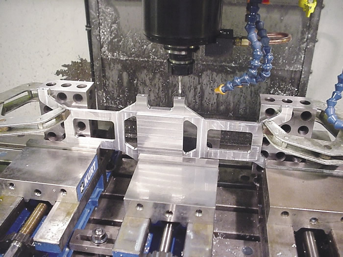
This part is held for edge drilling with the aid of 2-4-6 blocks. All images courtesy J. Harvey.

When presented with a part that is difficult to hold, your ingenuity will be put to the test. However, don’t spend time constructing complex fixtures when you don’t have to. When a standard vise won’t do the job, one option is conventional shop tooling, such as 1-2-3 blocks, 2-4-6 blocks, long parallels, grinding vises, angle plates and V-blocks. These items can effectively provide the added support you need.
Nonetheless, I’ve found that when I finally decide to build a custom fixture, I’m almost always glad I did. Often a fixture is needed to hold parts for perimeter cutting if the material is already at the correct thickness. In these cases, you can’t use excess stock to hold the part.
The following is a simple but effective trick for making fixtures you can bolt parts to. Suppose you are making a part that has no excess material to hold for cutting the perimeter, but has through-holes that can be used for clamping. When you are done drilling, manually tap the fixture through the holes in the part. After that, simply screw the part to the fixture. You are now ready to cut the perimeter. The beauty of this method is you never have to move the part.
Most fixtures can be constructed of aluminum. Our shop has a couple drawers full of simple fixtures that machinists have constructed for various jobs. One of our biggest problems with these fixtures is we don’t have enough room to store them, so they get scattered about, making them difficult to find.


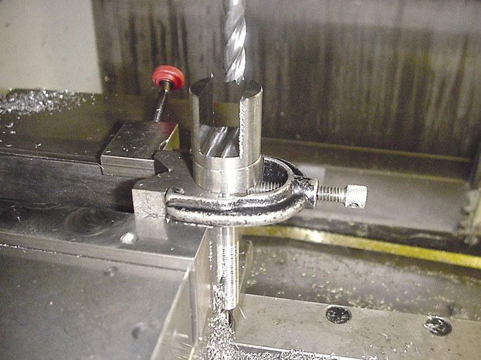
V-blocks provide a quick way to hold cylindrical parts for further machining.

We made the mistake some years ago of buying two cheap, low-quality milling machine vises. Our thinking was, “All the vise has to do is clamp the part. How difficult can that be?” We suffered with these vises for about a year before we upgraded to high-quality vises. With a loose-tolerance milling vise constructed of low-quality metal, we constantly struggled to hold parts securely against parallels, and the vise had a lot of sharp edges and burrs. In addition, there was a “spongy” feel when you started to clamp a part. You were never quite sure how much to tighten the vise, which resulted in inconsistent clamping pressure and part location. Even the handles didn’t fit properly. A milling machine vise is used nearly every day, which compounds the importance of having a good one.
One rule I always try to follow is don’t work blind if you don’t have to. Being able to see the cut allows you to keep an eye on cutters for anomalies—chip packing, chatter, improper coolant coverage, poor surface finish, cutter flex, gouging and jamming—before they become an issue. An added benefit is machined features will likely be easier to inspect.
Theoretically, you have stability when pressure applied anywhere perpendicular to an unclamped part doesn’t move the part. Having stability is more important when machining a flimsy part—the strength of the material may not provide enough rigidity to make a cut.
There are a few items to keep in mind when using V-blocks to hold parts. First, V-blocks don’t apply clamping pressure over a large surface area. The clamping pressure is applied to tangent lines on the part circumference. If you squeeze down too hard on a part held with a V-block, you may dent the part and throw the centerline of the part off location.
If you use two V-blocks to hold round parts, theoretically, you get four lines of clamping contact. If cutting pressures will be light, I often use just one V-block and a vise jaw to apply clamping pressure. In addition, placing soft material between the vise jaw and part prevents denting the part.
If the diameter of a cylindrical part is not precise and consistent, using a V-block to hold the part may cause it to tilt or throw the centerline off location. That’s one reason you shouldn’t always take advantage of wide-open tolerances. Tight tolerances, although not necessarily needed for the part to function, may be needed to accurately locate and hold workpieces for further
machining.
Perishable jaw vises can effectively hold parts, but should be considered a last resort. This is because it’s often difficult to find a set that hasn’t been cut up. You can always make new vise blanks, but if you leave them out, they’ll likely get used quickly. Also, the appropriate nests have to be machined into them, which consumes time.
Related Glossary Terms
- V-block
V-block
Workholding device with V-shaped slot for holding pipe and other round stock during machining or inspection.
- chatter
chatter
Condition of vibration involving the machine, workpiece and cutting tool. Once this condition arises, it is often self-sustaining until the problem is corrected. Chatter can be identified when lines or grooves appear at regular intervals in the workpiece. These lines or grooves are caused by the teeth of the cutter as they vibrate in and out of the workpiece and their spacing depends on the frequency of vibration.
- coolant
coolant
Fluid that reduces temperature buildup at the tool/workpiece interface during machining. Normally takes the form of a liquid such as soluble or chemical mixtures (semisynthetic, synthetic) but can be pressurized air or other gas. Because of water’s ability to absorb great quantities of heat, it is widely used as a coolant and vehicle for various cutting compounds, with the water-to-compound ratio varying with the machining task. See cutting fluid; semisynthetic cutting fluid; soluble-oil cutting fluid; synthetic cutting fluid.
- feed
feed
Rate of change of position of the tool as a whole, relative to the workpiece while cutting.
- fixture
fixture
Device, often made in-house, that holds a specific workpiece. See jig; modular fixturing.
- gang cutting ( milling)
gang cutting ( milling)
Machining with several cutters mounted on a single arbor, generally for simultaneous cutting.
- grinding
grinding
Machining operation in which material is removed from the workpiece by a powered abrasive wheel, stone, belt, paste, sheet, compound, slurry, etc. Takes various forms: surface grinding (creates flat and/or squared surfaces); cylindrical grinding (for external cylindrical and tapered shapes, fillets, undercuts, etc.); centerless grinding; chamfering; thread and form grinding; tool and cutter grinding; offhand grinding; lapping and polishing (grinding with extremely fine grits to create ultrasmooth surfaces); honing; and disc grinding.
- milling
milling
Machining operation in which metal or other material is removed by applying power to a rotating cutter. In vertical milling, the cutting tool is mounted vertically on the spindle. In horizontal milling, the cutting tool is mounted horizontally, either directly on the spindle or on an arbor. Horizontal milling is further broken down into conventional milling, where the cutter rotates opposite the direction of feed, or “up” into the workpiece; and climb milling, where the cutter rotates in the direction of feed, or “down” into the workpiece. Milling operations include plane or surface milling, endmilling, facemilling, angle milling, form milling and profiling.
- milling machine ( mill)
milling machine ( mill)
Runs endmills and arbor-mounted milling cutters. Features include a head with a spindle that drives the cutters; a column, knee and table that provide motion in the three Cartesian axes; and a base that supports the components and houses the cutting-fluid pump and reservoir. The work is mounted on the table and fed into the rotating cutter or endmill to accomplish the milling steps; vertical milling machines also feed endmills into the work by means of a spindle-mounted quill. Models range from small manual machines to big bed-type and duplex mills. All take one of three basic forms: vertical, horizontal or convertible horizontal/vertical. Vertical machines may be knee-type (the table is mounted on a knee that can be elevated) or bed-type (the table is securely supported and only moves horizontally). In general, horizontal machines are bigger and more powerful, while vertical machines are lighter but more versatile and easier to set up and operate.
- tap
tap
Cylindrical tool that cuts internal threads and has flutes to remove chips and carry tapping fluid to the point of cut. Normally used on a drill press or tapping machine but also may be operated manually. See tapping.


