Factors affecting proper coolant application when grinding

Author John A. Webster, Ph.D.
Published
August 11, 2017 - 03:00pm

Grinding is a thermally dominated process, meaning a high percentage of process heat initially enters the part before coolant quenches it. Unless the coolant is applied at the correct flow rate and pressure, and the proper input conditions are selected, this process can lead to undesirable rehardening burn, thermal softening and tensile residual stresses. 

By comparison, in a well-designed machining process, the majority of heat typically goes into the chips, not the part. Therefore, less cooling is needed, but the process requires more lubrication and effective chip evacuation, often involving a coolant pressure of 1,000 psi (69 bar) or higher and a low flow rate—8 gpm (30.3 L/min.) or less. 

In addition, grinding consumes three to five times more specific cutting energy than other types of machining operations to remove the same volume of material. Considerably more heat must be removed from the process to maintain part integrity. This big difference in energy consumption is because of the undefined cutting edges of the grinding wheel grit, the smaller chips produced and the friction among the bond, chips and workpiece material.  

A well-tested flow-rate model for grinding applies 1.5 to 2 gpm (5.7 to 7.6 L/min.) per spindle horsepower. An aggressive grinding process that consumes 20 hp would, therefore, require 30 to 40 gpm (113.6 to 151.4 L/min.) to keep the process cool. 

Clearing Air Barriers

Because grinding wheels reach far higher peripheral speeds than cutting tools, wheels have a more pronounced boundary layer of air surrounding them during operation. This air barrier can deflect coolant from the grinding zone unless the pump pressure is sufficient for the coolant jet from the nozzle to match the wheel speed and penetrate the barrier. 


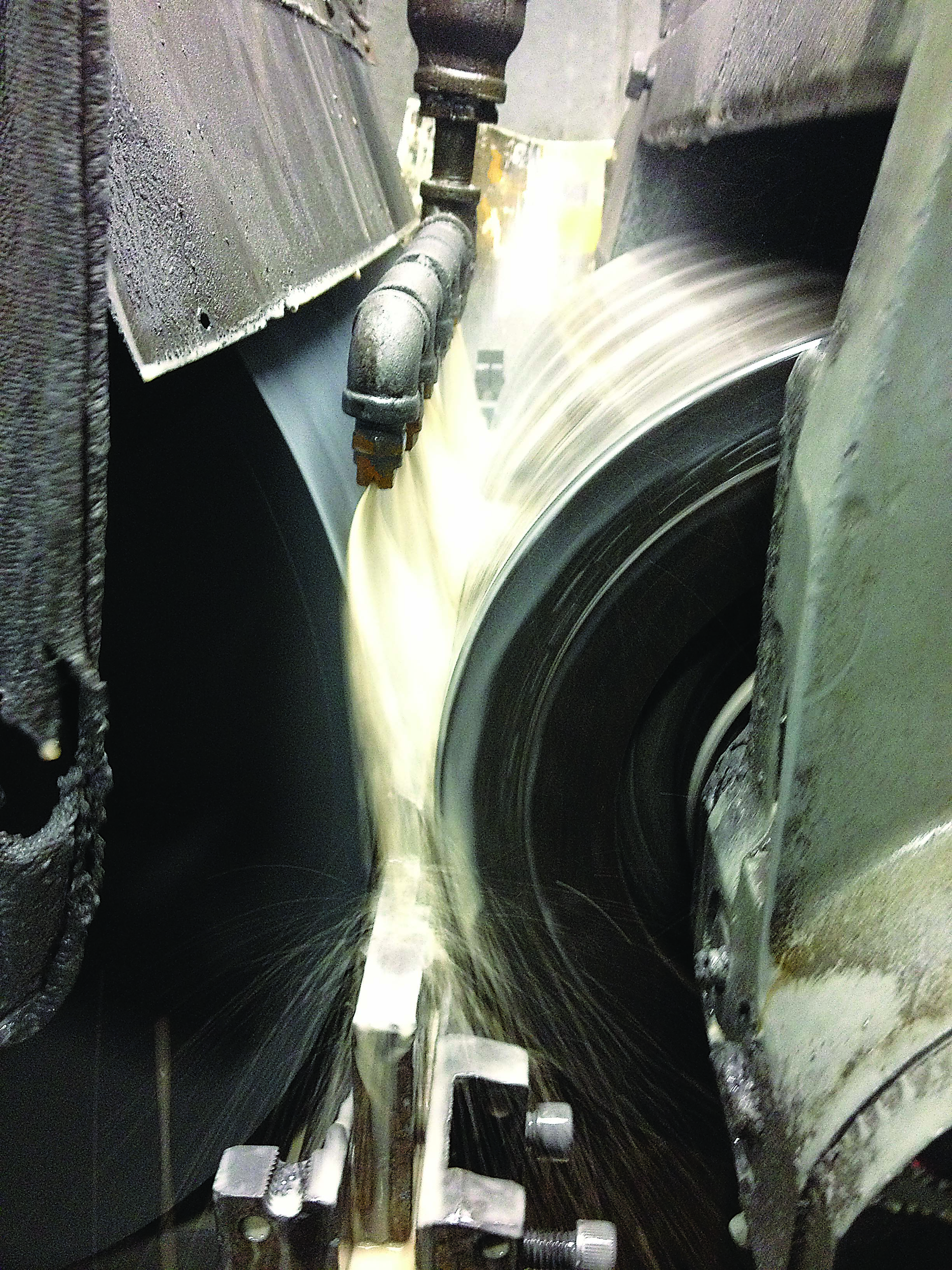
All images courtesy of Cool-Grind Technologies.


The photo (above) shows a centerless grinding process with a 10-psi (0.7-bar) coolant stream applied through a row of fan nozzles. The jets are aimed slightly toward the 6,000-sfm (1,829-m/min.) grinding wheel on the left side. The photo shows the air barrier deflecting the coolant toward the regulating wheel on the right side, with no coolant hugging the wheel and entering the grinding zone below. 

In centerless grinding, the air barrier creates the additional problem of lost friction between the regulating wheel and the workpiece. Lost friction leads to slippage between the regulating wheel and part and more frequent wheel truing to restore the worn drive surface. In all forms of grinding, wetting the wheel will allow the extreme-pressure additives in the coolant to do their job. The additives will keep forces and wheel wear low, create a cleaner wheel structure, reduce the amount of wheel dressing and allow more aggressive feed rates. 

Bernoulli’s energy equation can be used to predict the pressure that creates the desired jet velocity. For example, a grinding wheel moving at 12,000 sfm (3,657 m/min.) requires a nozzle pressure close to 270 psi (18.6 bar) for the coolant jet to match the wheel speed. Lower wheel speeds require lower pressures. The chart (below) shows the pressure required for water-based, synthetic oil and mineral oil coolants to achieve the desired jet speed.


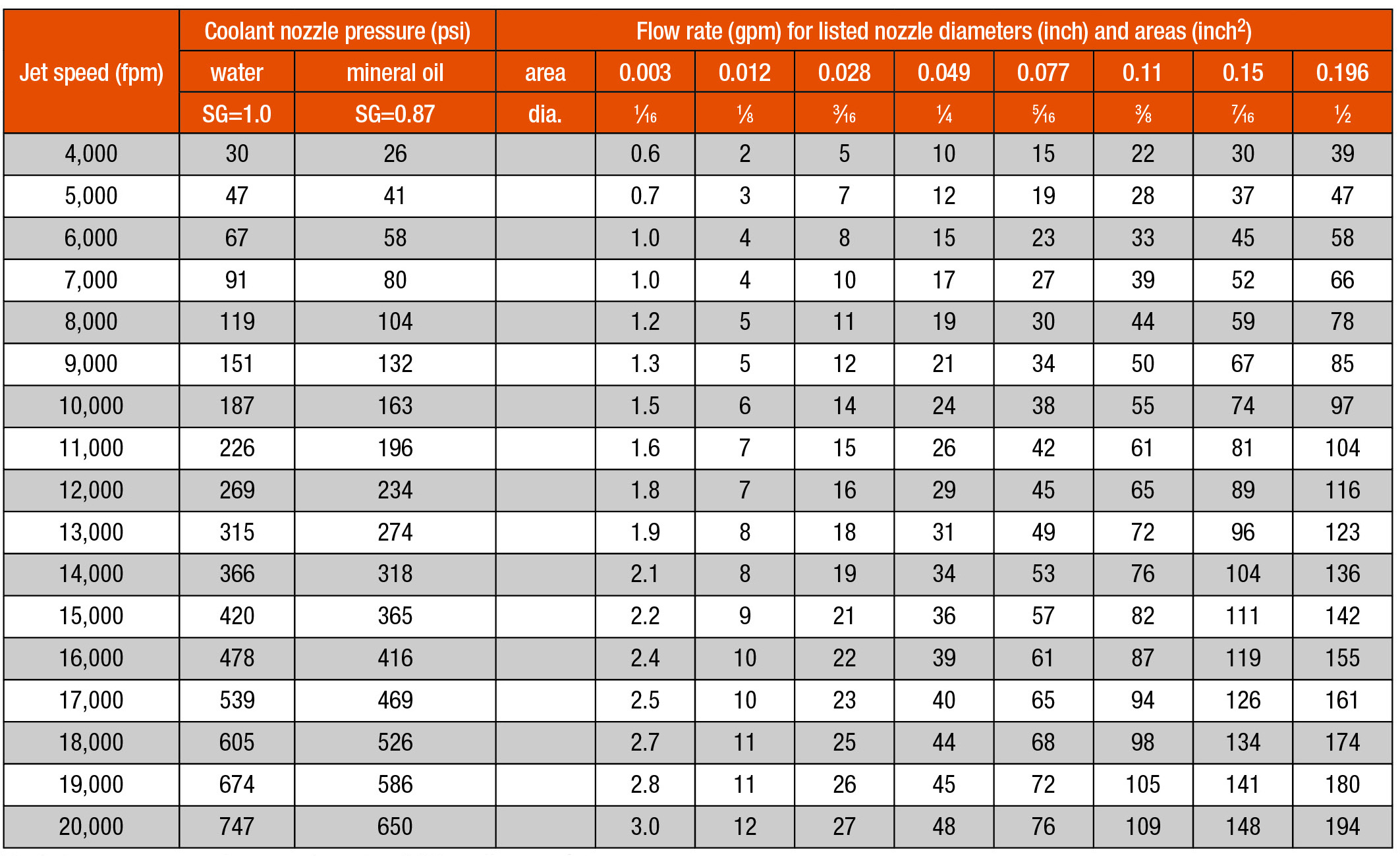
English flow-rate chart for a nozzle with a 0.95 coefficient of discharge.


Double-Pump Design

I have been asked many times to design a coolant nozzle to suit a high-pressure (1,000 psi or more), low-flow-rate pump that a customer has already purchased prior to contacting me—much like asking someone to sew a shirt onto a button. The customer assumes that if 1,000 psi is good for machining, it must be good for grinding. This type of pump is  expensive and will insufficiently cool the process because of its low flow rate. However, it will keep the wheel structure clean and free cutting, providing some benefits. 

Unless the aperture of the nozzle is small enough, the pressure developed by the high-pressure pump will be much lower than the 1,000 psi it is capable of producing. As a result, money will be wasted buying a pump whose capabilities aren’t fully utilized. 

The internal geometry of the nozzle will also need to have a high coefficient of discharge to control the quality of the jet and prevent flow dispersion and air entrainment.

A more effective and less expensive approach is to incorporate two pumps in the coolant system. Work with both a low-pressure (60 to 300 psi, or 4.1 to 20.7 bar), high-flow-rate, centrifugal pump for cooling and a high-pressure, low-flow-rate pump for wheel cleaning, with nozzles of suitable aperture and width to apply the correct flow rate and pressure from each pump. The best strategy is to optimize the low-pressure system first. Then see if the wheel structure becomes loaded with chips before investing in a high-pressure scrubber nozzle and high-pressure pump. 


A diagram of a dual-pump coolant systemfor grinding.


The block diagram (above) shows a dual-pump coolant system from Cool-Grind Technologies. Coolant from the central or individual-grinder coolant system is fed into the dual-pump metal enclosure and distributed to the inlet of each pump. A relief valve is fitted to the output of the high-pressure pump to control the pressure. This valve also guards against a blocked nozzle dead-heading the positive-displacement pump, leading to mechanical damage. 

A bypass valve controls the pressure from the low-pressure centrifugal pump, which directs coolant to the tangential nozzle, with both circuits returning excess clean coolant to the filtration system. A 5µm cartridge filter in the high-pressure pump circuit minimizes the risk of blocking the small apertures of the scrubber nozzles. 

The output pressures from the high-pressure and low-pressure pumps are displayed on gages located on the outside of the enclosure. The complete dual-pump system is easily integrated into the grinding machine control and power circuits. The unit has casters for moving it from one grinding machine to another. It is also fitted with quick-disconnect hose fittings. 

Scrubbing Nozzles

There has been little published research—or application studies—on wheel scrubbing and the required nozzles. Typically, 600 to 800 psi (41.4 to 55.2 bar) is the maximum pressure recommended for vitrified- and resin-bond wheels, and up to 1,500 psi (103.4 bar) is suitable for the more resilient electroplated and metal-bond superabrasive wheels. Manufacturers of highly friable wheel structures for grinding carbide may recommend lower pressures to prevent premature wheel breakdown. 

A specific flow rate of 2 to 3 gpm (7.6 to 11.4 L/min.) per inch of wheel width is adequate to keep the wheel structure clean. The jet streams should be directed radial to or slightly opposing the wheel direction in order to remove chips from the front of the abrasive grit. If the scrubber nozzle is mounted just before the low-pressure cooling nozzle, the jet can also peel off the air barrier before the lower-pressure tangential jet hits the wheel.


This scrubber nozzle requires a ¼" NPT thread to attach it to a grinding machine (¼ MEG). The 4006 marking means the nozzle has a 40° fan angle and a 6-gpm flow rate at 4,000 psi.


High-pressure scrubber nozzles are typically the flat-fan type, where the width of the fan increases with distance from the wheel. The photo (above) shows a typical scrubber nozzle, which is marked on the tip with the fan angle and the aperture size. The marking 4006 means a 40° fan angle and a 6 gpm (22.7 L/min.) flow rate at 4,000 psi (275.8 bar). 

Bernoulli’s energy equation is a square law. Therefore, at a pressure of 1,000 psi, the nozzle will flow half of 6 gpm, or 3 gpm, at 4,000 psi, sufficient for a 1"-wide (25.4mm) grinding wheel. For the 40° fan to cover a 1"-wide wheel, the tip of the nozzle should be at least 1.4" (35.6mm) from the wheel surface. 

Other available fan angles are 15°, 25° and 65°. Flow rates from these nozzles can range from 2 to 50 gpm (7.6 to 189.3 L/min.) at 4,000 psi. The ¼ MEG marking on the nozzle means a ¼" NPT thread is used to attach the nozzle to a machine.

By effectively applying coolant when grinding, end users should find the metal removal process to be less abrasive. 

Related Glossary Terms

  • abrasive

    abrasive

    Substance used for grinding, honing, lapping, superfinishing and polishing. Examples include garnet, emery, corundum, silicon carbide, cubic boron nitride and diamond in various grit sizes.

  • centerless grinding

    centerless grinding

    Grinding operation in which the workpiece rests on a knife-edge support, rotates through contact with a regulating or feed wheel and is ground by a grinding wheel. This method allows grinding long, thin parts without steady rests; also lessens taper problems. Opposite of cylindrical grinding. See cylindrical grinding; grinding.

  • coolant

    coolant

    Fluid that reduces temperature buildup at the tool/workpiece interface during machining. Normally takes the form of a liquid such as soluble or chemical mixtures (semisynthetic, synthetic) but can be pressurized air or other gas. Because of water’s ability to absorb great quantities of heat, it is widely used as a coolant and vehicle for various cutting compounds, with the water-to-compound ratio varying with the machining task. See cutting fluid; semisynthetic cutting fluid; soluble-oil cutting fluid; synthetic cutting fluid.

  • dressing

    dressing

    Removal of undesirable materials from “loaded” grinding wheels using a single- or multi-point diamond or other tool. The process also exposes unused, sharp abrasive points. See loading; truing.

  • feed

    feed

    Rate of change of position of the tool as a whole, relative to the workpiece while cutting.

  • grinding

    grinding

    Machining operation in which material is removed from the workpiece by a powered abrasive wheel, stone, belt, paste, sheet, compound, slurry, etc. Takes various forms: surface grinding (creates flat and/or squared surfaces); cylindrical grinding (for external cylindrical and tapered shapes, fillets, undercuts, etc.); centerless grinding; chamfering; thread and form grinding; tool and cutter grinding; offhand grinding; lapping and polishing (grinding with extremely fine grits to create ultrasmooth surfaces); honing; and disc grinding.

  • grinding machine

    grinding machine

    Powers a grinding wheel or other abrasive tool for the purpose of removing metal and finishing workpieces to close tolerances. Provides smooth, square, parallel and accurate workpiece surfaces. When ultrasmooth surfaces and finishes on the order of microns are required, lapping and honing machines (precision grinders that run abrasives with extremely fine, uniform grits) are used. In its “finishing” role, the grinder is perhaps the most widely used machine tool. Various styles are available: bench and pedestal grinders for sharpening lathe bits and drills; surface grinders for producing square, parallel, smooth and accurate parts; cylindrical and centerless grinders; center-hole grinders; form grinders; facemill and endmill grinders; gear-cutting grinders; jig grinders; abrasive belt (backstand, swing-frame, belt-roll) grinders; tool and cutter grinders for sharpening and resharpening cutting tools; carbide grinders; hand-held die grinders; and abrasive cutoff saws.

  • grinding wheel

    grinding wheel

    Wheel formed from abrasive material mixed in a suitable matrix. Takes a variety of shapes but falls into two basic categories: one that cuts on its periphery, as in reciprocating grinding, and one that cuts on its side or face, as in tool and cutter grinding.

  • relief

    relief

    Space provided behind the cutting edges to prevent rubbing. Sometimes called primary relief. Secondary relief provides additional space behind primary relief. Relief on end teeth is axial relief; relief on side teeth is peripheral relief.

  • truing

    truing

    Using a diamond or other dressing tool to ensure that a grinding wheel is round and concentric and will not vibrate at required speeds. Weights also are used to balance the wheel. Also performed to impart a contour to the wheel’s face. See dressing.

Author

Owner, Cool-Grind Technologies LLC
860-429-8822

John A. Webster, Ph.D., aka Dr. Cool, is the owner and founder of Cool-Grind Technologies LLC, Storrs, Conn. For more information about coolant application for grinding, call 860-429-8822 or visit www.cool-grind.com.